
Lighting apparatus and illuminating fixture with the same

A technology of equipment and inductors, which is applied in the field of lighting appliances, can solve the problems of undisclosed dimming circuit structure, flickering, short turn-on time, etc.

Inactive Publication Date: 2013-06-05
PANASONIC CORP
View PDF7 Cites 9 Cited by
  • Summary
  • Abstract
  • Description
  • Claims
  • Application Information

AI Technical Summary

Problems solved by technology

However, Document 2 does not disclose the specific circuit structure used for dimming
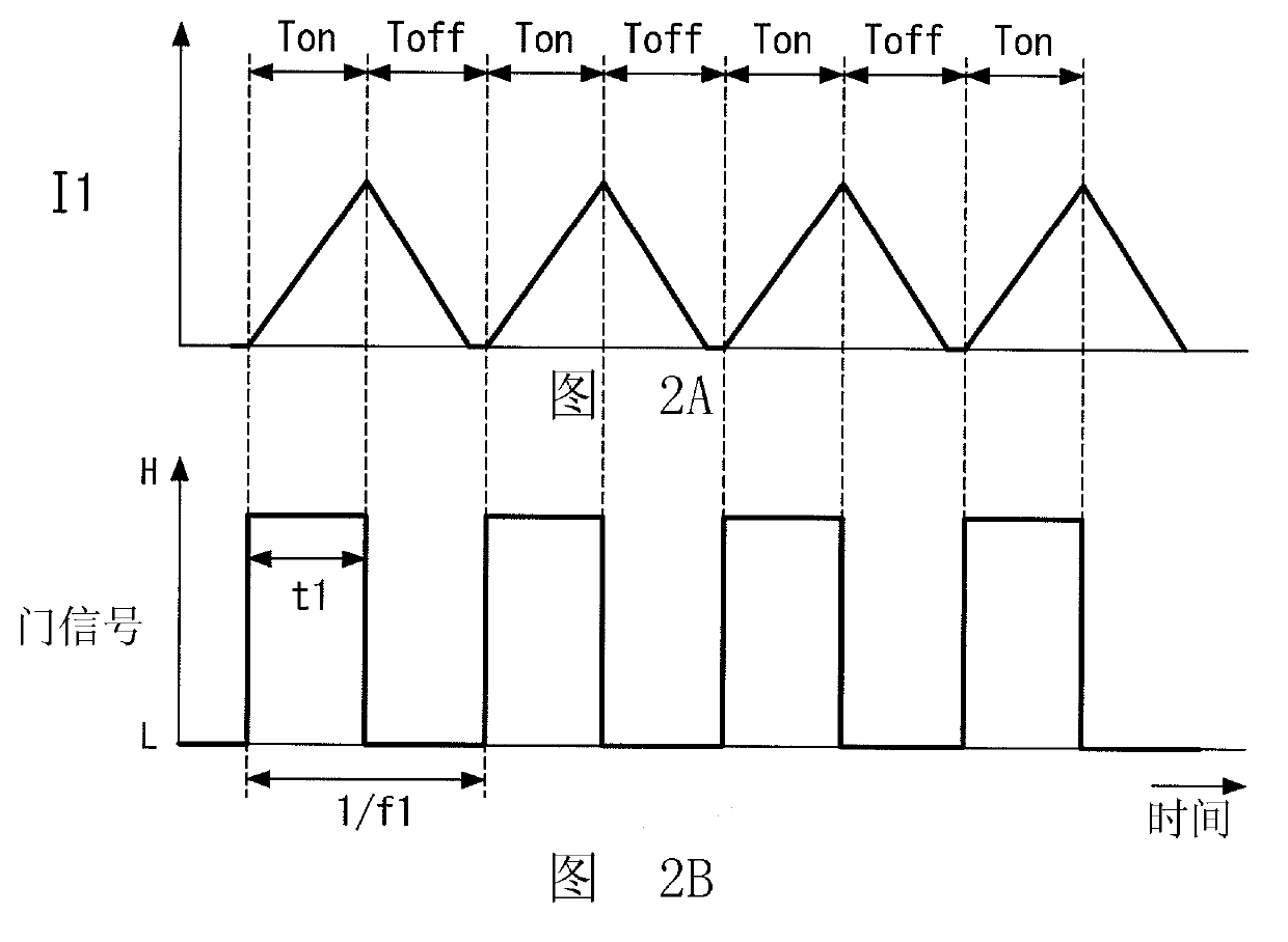
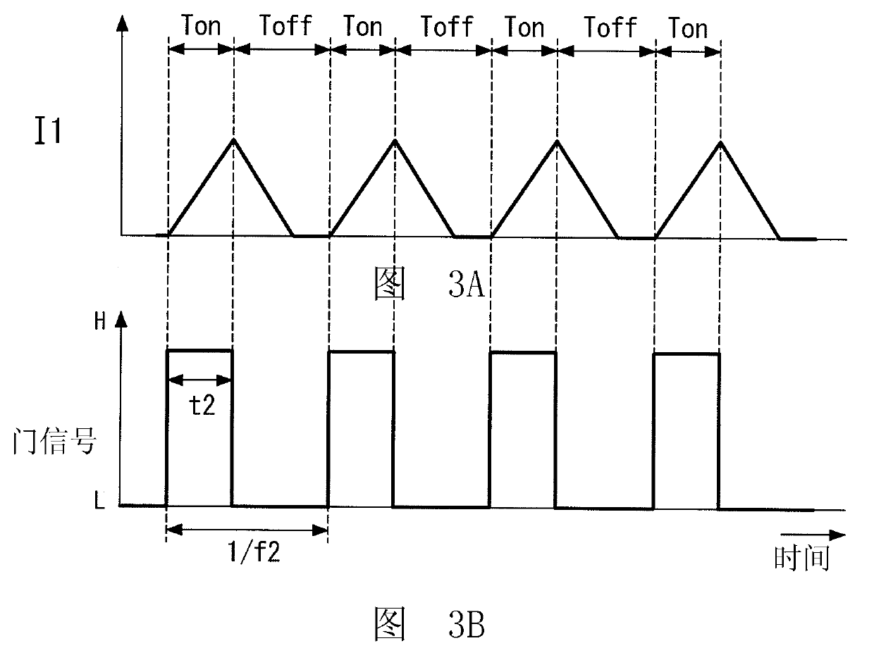
[0005] However, as described in Document 2, in a lighting device for dimming by controlling the pulse length (on time), when the dimming ratio is relatively small (dark), one period of the burst frequency within a short on-time, which may cause flicker
For this reason, in this lighting device, it is difficult to set a wide range of selectable dimming ratios

Method used


Image

  • Lighting apparatus and illuminating fixture with the same
  • Lighting apparatus and illuminating fixture with the same
  • Lighting apparatus and illuminating fixture with the same

Examples


no. 1 example

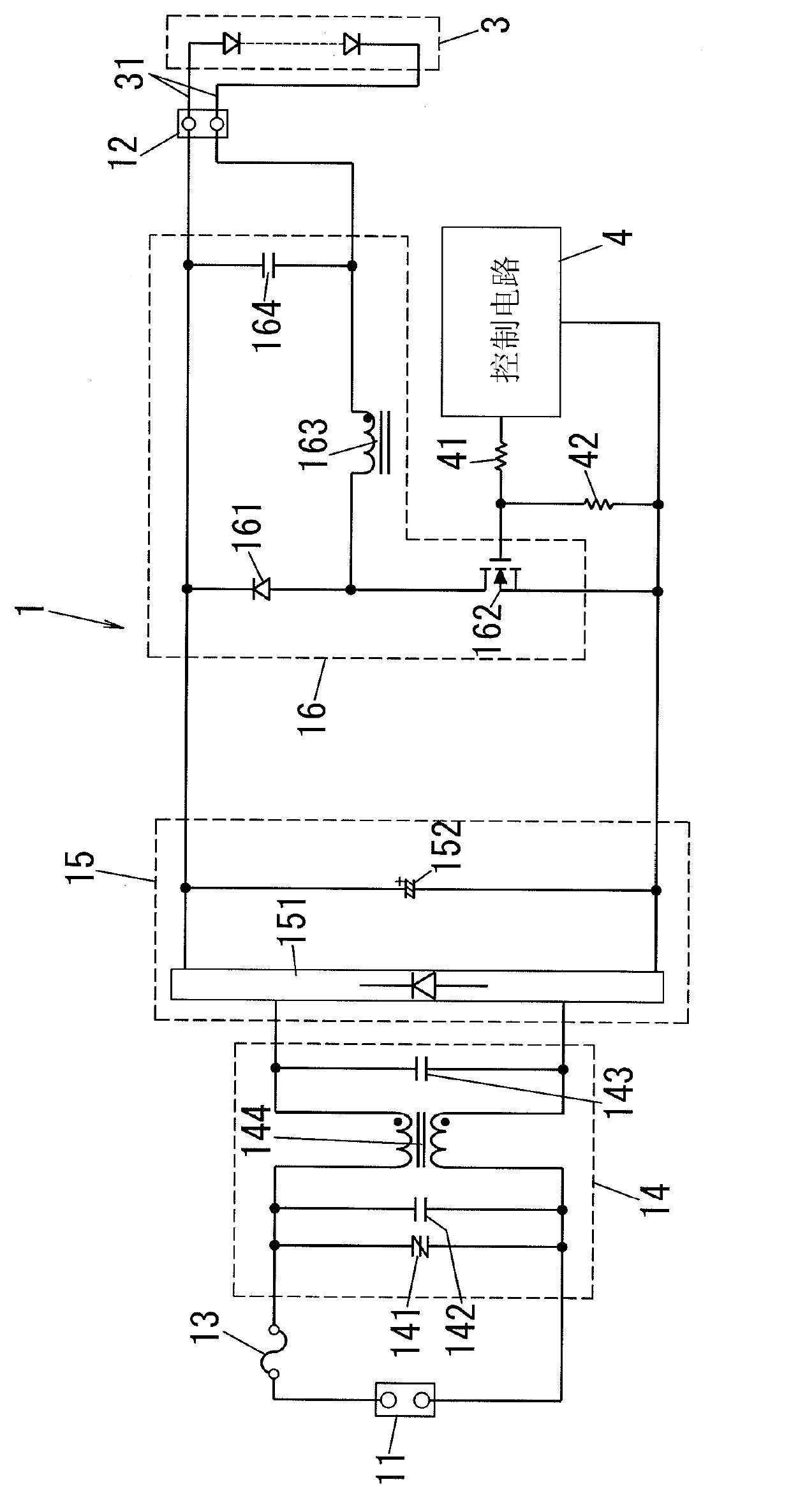
[0030] Such as figure 1 As shown, the lighting device 1 according to the embodiment of the present invention includes: a power connector 11 for connecting to an AC power source 2 such as a commercial power source (see Figure 8 ); and an output connector 12 for connecting to a light source load 3 including a semiconductor light emitting element such as a light emitting diode (LED) via a lead wire 31. The light source load 3 is configured to be lit with a DC (direct current) output current supplied from the lighting device 1 . The light source load 3 may be an LED module composed of multiple (for example, 30) light emitting diodes connected in series, parallel or series-parallel.

[0031] The lighting device 1 includes the following components as main components: a DC power generation unit having a filter circuit 14 and a DC power circuit 15 ; a step-down chopper circuit (step-down converter) 16 ; and a control circuit 4 . The following will refer to figure 1 The basic struc...

no. 2 example

[0094] Such as Figure 10 As shown, the lighting device 1 according to the present embodiment differs from the lighting device 1 according to the first embodiment in the structure of the control circuit 4 and the power supply circuit 7 for control. exist Figure 10 In the example of , the external dimmer 6 outputting a 5V, 1kHz rectangular wave voltage signal as a dimming signal is connected to the signal line connector 17 of the lighting device 1 via the dimming signal line 5 . Hereinafter, the same components as those of the first embodiment are denoted by the same reference numerals, and descriptions for these components will not be repeated here.

[0095] In the present embodiment, the DC power supply circuit 15 includes a step-up chopper circuit as a power factor improvement circuit provided at the output terminal of the full-wave rectifier 151 . This step-up chopper circuit includes a general structure in which an inductor 153 and a switching element 154 are connected ...


PUM


Abstract

The invention relates to a lighting apparatus and an illuminating fixture with the same. A control circuit selects a first control mode in which a switching element is turned on and off so that a current flows through an inductor in a critical or discontinuous mode, thereby fully lighting a light source load. The control circuit selects one of a second control mode in which on time of the switching element is changed and a third control mode in which an oscillating frequency is changed according to an interval, to which a designated dimming ratio corresponds, to dim the light source load. An output capacitor connected between output terminals of a step-down chopper circuit smoothes pulsation component of an output current supplied to the light source load and has capacity set so that a ripple ratio of the output current is less than 0.5 at full lighting of the light source load.

Description

technical field [0001] The invention relates to a lighting device capable of dimming a semiconductor light-emitting element and a lighting fixture with the lighting device. Background technique [0002] Recently, lighting fixtures using semiconductor light emitting elements such as light emitting diodes (LEDs) and organic electroluminescence (ELs) as light sources have become widespread. Such a lighting fixture is provided with, for example, a lighting device (LED lighting device) disclosed in Japanese Patent Laid-Open No. 2005-294063 (hereinafter referred to as "document 1"). [0003] The lighting device in Document 1 is a self-excited type lighting device and does not have a dimming function. Therefore, it is not possible to dim the light source load. [0004] On the other hand, International Publication No. WO 01 / 58218 A1 (hereinafter referred to as "Document 2") discloses that: The burst frequency is used to turn on and off the power supply to the light source load (L...

Claims


Application Information

Patent Timeline
Patent Type & Authority Applications(China)
IPC IPC(8): H05B37/02H05B44/00
CPCH05B33/08H05B33/0815H05B45/382H05B45/38H05B45/375H05B45/3725H05B45/385
Inventor 江崎佐奈平松明则
Owner PANASONIC CORP
Learn More