Stand for surgical microscope

A surgical microscope and microscope technology, applied in surgical microscopes, operating tables, surgery, etc., can solve the problems of surgical microscope repositioning, disorientation, time loss, etc., and achieve the effects of weight reduction, compact structure, and cost reduction

Inactive Publication Date: 2013-06-12
LEICA MICROSYSTEMS (SCHWEIZ) AG
View PDF4 Cites 29 Cited by
  • Summary
  • Abstract
  • Description
  • Claims
  • Application Information

AI Technical Summary

Problems solved by technology

[0009] If the surgeon does not have the required skill / practice and the magnification adjusted at the surgical microscope can be very high, then despite the leveraged support due to the simple (possibly even only slightly) higher positioning of the surgical microscope, the target or the surgical field disappears rapidly from the center of the viewing area or completely disappears from the viewing area
This can cause disorientation and require repositioning of the operating microscope
However, this leads to a loss of time during the operation, which on the one hand is undesirable and on the other hand can even be disadvantageous for the operation itself

Method used


Image

  • Stand for surgical microscope
  • Stand for surgical microscope
  • Stand for surgical microscope

Examples


Embodiment Construction

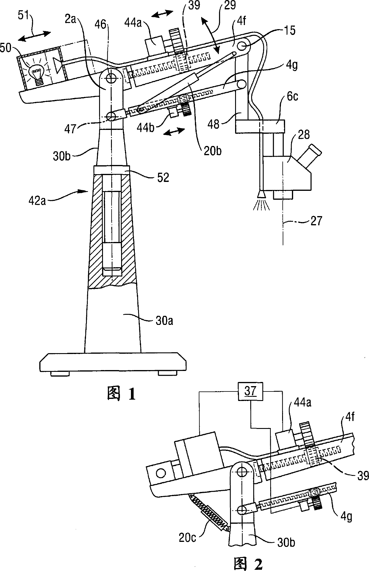
[0124] figure 1 Shows a traditional stand according to document DE10042272A1, however with the extensibility according to the invention of the arms or rather the parts 4f, 4g of the arms (which are assembled with their proximal and distal ends into parallelogram arms) . The two parts 4f and 4g of the arm thus form the upper and lower layers of the double-layer arm. Each of the arm parts 4f and 4g is configured to be retractable (preferably simultaneously and equally far) so that the axis of rotation 46 at the distal and proximal sides of these arm parts 4f, 4g can be increased or decreased or the distance between 47. These length changes are usually carried out synchronously and isometrically, but within the scope of the invention there are also special embodiments in which the two sub-arms can be moved out by different lengths in order to thus realize the microscope holder 6c (which connected to the distal ends of the parts 4f and 4g of the arms via supports 48) in any pos...


PUM


Abstract

The invention relates to a stand for a surgical microscope (28) having a pivotable carrier arm (4). The latter is modifiable in length as a function of its pivot angle (29). It carries a microscope holder (6), pivotable in at least one plane, at the distal end of carrier arm (4), the angular position (21; 24) of the microscope holder (6) being definable with reference to the carrier arm (4; 34) according to a further development; and a motorized drive, which engages on the one hand on the carrier arm and on the other hand on the microscope holder (6), and in the context of operation defines the angular position (21; 24) in remotely controlled fashion and / or automatically.

Description

technical field [0001] The invention relates to a pedestal (Stativ) (operating table pedestal) for an operating microscope (Operationsmikroskop) with an optical main axis according to the preamble of claim 1, with a pivotable A support arm and a microscope mount (Mikroskophalter) for accommodating a surgical microscope at the distal end of the support arm, pivotable in at least one plane at the support arm, wherein the support arm has a determinable angular position relative to the pivot bearing , so as to thereby adjust the relative angular position of the support arm with respect to the horizontal. Such a support arm is described, for example, in DE 10 2008 011 639 A1. Since the support arm is directly or indirectly connected to the building part or rests on the ground, a separate adjustment of this relative angular position also always results in an adjustment of the main axis relative to the plumb line (Lot). In the case of a vertically oriented tracking of the surgical ...

Claims


Application Information

Patent Timeline
Patent Type & Authority Applications(China)
IPC IPC(8): A61B19/02G02B7/00F16M11/10F16M11/42
CPCA61B2019/265A61G13/00A61B2019/266A61B19/00F16M2200/044F16M11/2092F16M11/18F16M11/00A61B19/26F16M11/2064A61B2090/506A61B90/25A61B90/50A61B2090/508F16M2200/063
Inventor R·弗里克U·桑德M·舒茨
Owner LEICA MICROSYSTEMS (SCHWEIZ) AG
Why Eureka
Try Eureka