Punching machine suitable for cloth, leather and artificial leather

A punching machine and leather material technology, applied in the field of punching machines, can solve problems such as low punching accuracy, low efficiency, and insufficient punching accuracy, so as to avoid incomplete cutting, improve punching accuracy, and make up for adverse effects Effect

Inactive Publication Date: 2013-06-12
广州市集盛服饰皮具有限公司
View PDF7 Cites 10 Cited by
  • Summary
  • Abstract
  • Description
  • Claims
  • Application Information

AI Technical Summary

Problems solved by technology

Not only is the efficiency low, but also the punching accuracy is low, which affects the quality of the final product. The prior art discloses a punching machine suitable for cloth, leather and leather. There are punching knife, punching plate and driving mechanism in the frame. The punching plate can be installed in the frame up and down and impact on the punching knife. The driving mechanism drives the punching plate to move up and down. The end of the punching knife is a plane, and the punching plate It has a flat surface, the surface of the punching plate is parallel to the plane of the end of the punching knife, and the surface area of ​​the punching plate is larger than the plane area formed by the end of the punching knife. The defect of the punching machine with this structure

Method used


Image

  • Punching machine suitable for cloth, leather and artificial leather
  • Punching machine suitable for cloth, leather and artificial leather
  • Punching machine suitable for cloth, leather and artificial leather

Examples


Embodiment Construction

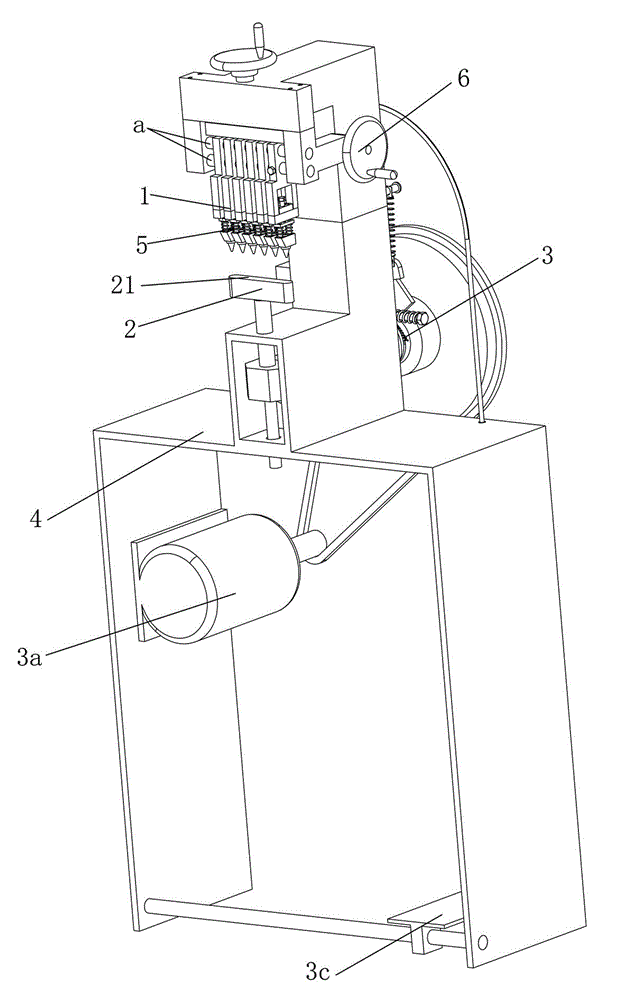
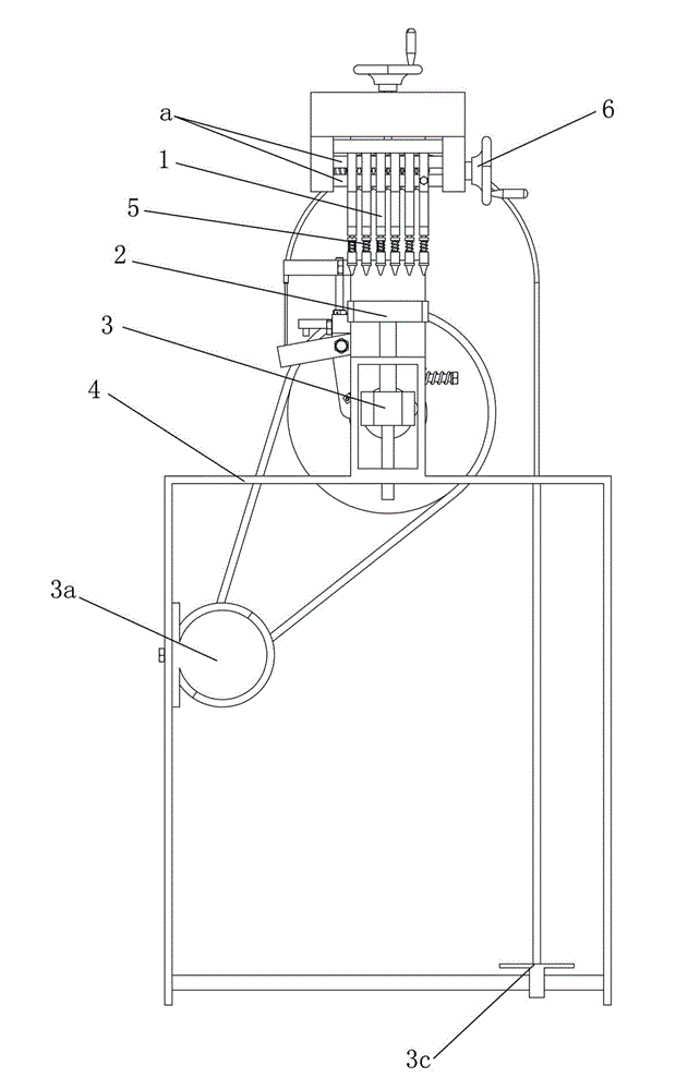
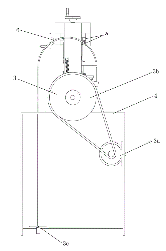
[0020] Such as figure 1 , figure 2 , image 3 The shown embodiment of the punching machine applicable to cloth, leather and leather of the present invention includes a frame 4 in which a punching knife 1, a punching plate 2 and a driving mechanism 3 are arranged, and the punching plate 2 can move up and down It is installed in the frame 4 and impacts on the punching knife 1. The driving mechanism 3 drives the punching plate 2 to move up and down. The end of the punching knife 1 is a plane equal to the pre-processed punching area, and the punching plate 2 has a flat surface. 21. The punching plate surface 21 is parallel to the plane at the end of the punching knife 1. The area of ​​the punching plate surface 21 is larger than the plane area formed at the end of the punching knife 1. The frame 4 has an elastic member 5 acting on the punching knife 1. The punching knife 1 has only The stationary station under the action of the elastic component 5 and the up and down micro-move...


PUM


Abstract

The invention provides a punching machine which is uniform in impact and excellent in punching precision and punching effect, and suitable for cloth, leather and artificial leather, and is especially capable of improving the punching precision and the punching effect aiming at multiple holes. The punching machine provided by the invention comprises a rack, wherein a punching cutter, a punching plate and a drive mechanism are arranged in the rack; the punching plate is movably arranged in the rack up and down and impacts the punching cutter; the punching plate is driven to move up and down by the drive mechanism; the tail end of the punching cutter is in a plane shape of which the area is equal to the area of a punching hole to be processed; the punching plate comprises a surface in a plane shape; the surface of the punching plate is parallel to the plane of the tail end of the punching cutter; the surface area of the punching plate is larger than the area of the plane formed at the tail end of the punching cutter; the rack comprises an elastic component acting on the punching cutter; and the punching cutter comprises a static station under the action of the elastic component only, and comprises an up and down microstroke under the combined action of the punching plate and the elastic component.

Description

technical field [0001] The invention relates to a punching machine, in particular to a semi-automatic punching machine suitable for punching holes in cloth, leather and leather. Background technique [0002] Existing perforated part, many finishes by manual drilling. Not only is the efficiency low, but also the punching accuracy is low, which affects the quality of the final product. The prior art discloses a punching machine suitable for cloth, leather and leather. There are punching knife, punching plate and driving mechanism in the frame. The punching plate can be installed in the frame up and down and impact on the punching knife. The driving mechanism drives the punching plate to move up and down. The end of the punching knife is a plane, and the punching plate It has a flat surface, the surface of the punching plate is parallel to the plane of the end of the punching knife, and the surface area of ​​the punching plate is larger than the plane area formed by the end of...

Claims


Application Information

Patent Timeline
IPC IPC(8): B26F1/02B26F1/14B26D5/08B26D7/02D06H7/00C14B5/00C14B17/10C14B17/08
Inventor 兰如林
Owner 广州市集盛服饰皮具有限公司
Why Eureka
Try Eureka