Busbar Heat Shrink Tube Hole Cutter

A heat-shrinkable tube and hole-cutting technology, used in metal processing and other directions, can solve the problems of slow efficiency and irregular incision, and achieve the effect of regular round holes and improved hole-cutting efficiency.

Active Publication Date: 2017-04-05
STATE GRID CORP OF CHINA +1
View PDF6 Cites 0 Cited by
  • Summary
  • Abstract
  • Description
  • Claims
  • Application Information

AI Technical Summary

Problems solved by technology

The traditional process is to use a circular template, align its center with the center hole and then cut along the outer edge of the circular template. Not only is the efficiency slow, but the incision is irregular

Method used


Image

  • Busbar Heat Shrink Tube Hole Cutter
  • Busbar Heat Shrink Tube Hole Cutter
  • Busbar Heat Shrink Tube Hole Cutter

Examples


Embodiment Construction

[0020] The content of the present invention will be described in detail below in conjunction with the accompanying drawings and embodiments of the description:

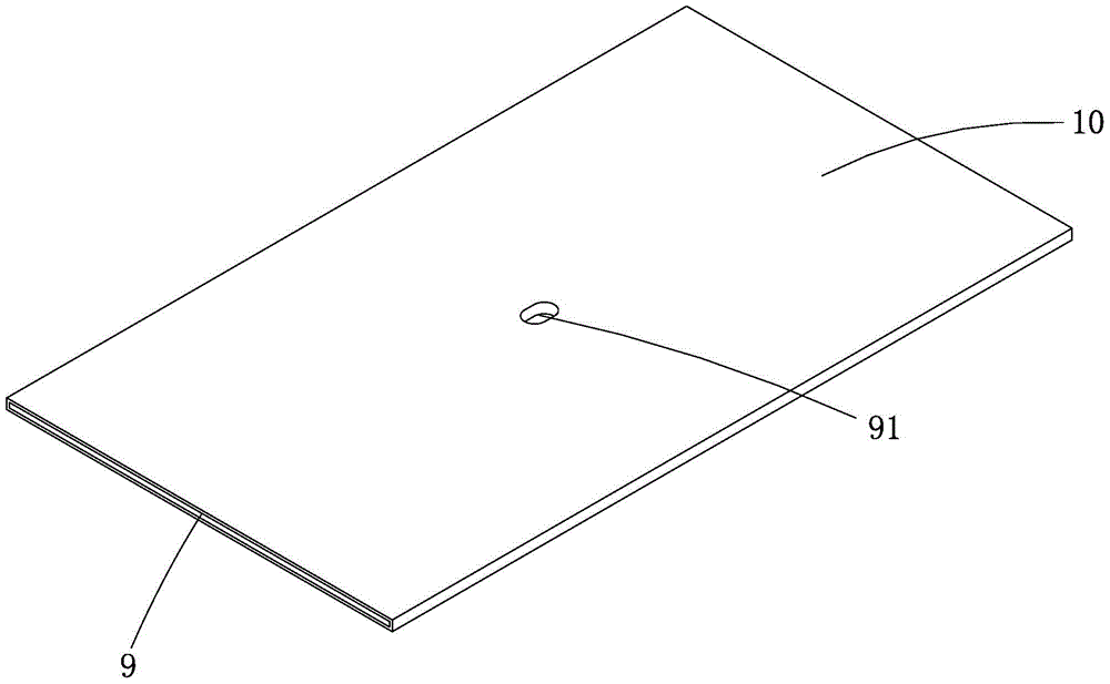
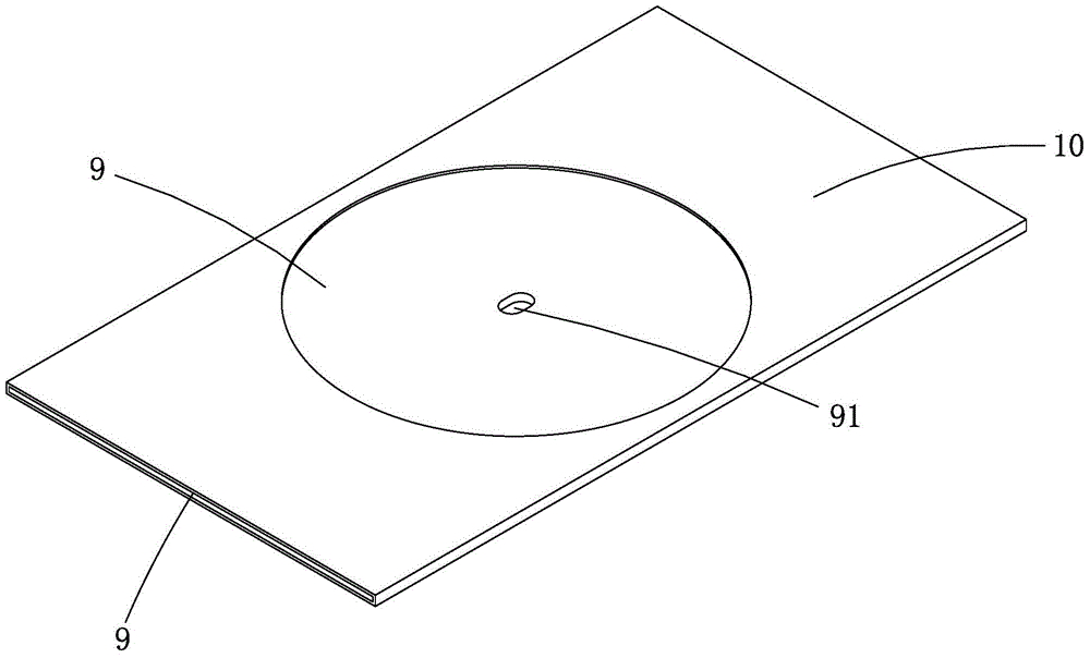
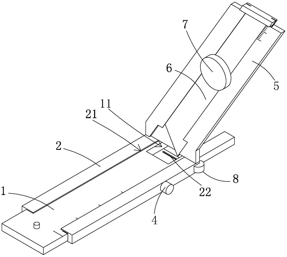
[0021] Such as Figure 3 to Figure 9 Shown is a schematic diagram of an embodiment of a busbar heat-shrinkable tube cutter provided by the present invention, which includes a telescopic rotating assembly and a knife assembly vertically arranged on the telescopic rotating assembly;

[0022] The telescopic rotating assembly includes a positioning plate 1, a sliding sleeve 2 slidingly sleeved on the positioning plate 1, a positioning block 3 hinged on the front bottom surface of the positioning plate 1, and a locking piece A4 for locking the sliding sleeve 2 and the positioning plate 1 The knife feed assembly includes a blade fixing slide rail 5 fixed on the rear end of the sliding sleeve 2, a blade feed 6 slidingly arranged on the blade fixing slide rail 5, and a tool for locking the blade fixing slide rail 5 and the bl...


PUM


Abstract

The invention relates to a busbar heat-shrinkable tube hole cutting device. The busbar heat-shrinkable tube hole cutting device comprises a telescopic rotating assembly and a feed assembly which is perpendicularly arranged on the telescopic rotating assembly. The telescopic rotating assembly comprises a positioning plate, a sliding sleeving part, a positioning block and a locking part A, wherein the positioning plate is sleeved with the sliding sleeving part in a sliding mode, the positioning block is hinged to the bottom surface of the front side of the positioning plate, and the locking part A is used for locking the sliding sleeving part and the positioning plate. The feed assembly comprises a blade fixing sliding rail, a feed blade and a locking part B, wherein the blade fixing sliding rail is fixedly arranged at the rear end of the sliding sleeving part, the feed blade is arranged on the blade fixing sliding rail in a sliding mode, and the locking part B is used for locking the blade fixing sliding rail and the feed blade. The feed direction of the feed blade is perpendicular to the positioning plate, and the feed blade penetrates out of the bottom of the telescopic rotating assembly. The busbar heat-shrinkable tube hole cutting device is simple in structure and convenient to operate. The busbar heat-shrinkable tube hole cutting device has the advantages that the hole cutting efficiency is greatly improved, and generated circular holes are regular and attractive.

Description

technical field [0001] The invention relates to a hole cutter for heat-shrinkable tubes of busbars. Background technique [0002] In order to install the sensor in the heat shrinkable tube of the busbar, a center hole needs to be opened on the upper side of the heat shrinkable tube of the busbar, and then a circular through hole is cut out of the heat shrinkable tube with the center hole as the center, and the sensor is placed in the circular through hole contact with the busbar. The traditional process is to use a circular formwork, align the center of the circle with the center hole and then cut along the outer edge of the circular formwork. Not only is the efficiency slow, but the incision is irregular. Contents of the invention [0003] The object of the present invention is to provide a heat-shrinkable tube hole cutter for busbars with simple structure and convenient operation. [0004] The object of the present invention is achieved through the following technical ...

Claims


Application Information

Patent Timeline
Patent Type & Authority Patents(China)
IPC IPC(8): B26F1/16B26D5/10B26D7/26
CPCB26D5/10B26D7/26B26F1/16
Inventor 林建森李爱民
Owner STATE GRID CORP OF CHINA
Why Eureka
Try Eureka