Laser positioning compass

A laser positioning and compass technology, used in circular curve plotters, anti-slip devices, printing and other directions, can solve problems such as the inability of compasses to be used alone, stabs at the metal feet of people's tips, affecting the accuracy of drawing circles, etc., and achieves a simple structure. , improve efficiency, and draw circles accurately

Inactive Publication Date: 2013-06-12
EAST CHINA UNIV OF TECH
View PDF5 Cites 8 Cited by
  • Summary
  • Abstract
  • Description
  • Claims
  • Application Information

AI Technical Summary

Problems solved by technology

[0002] Compass is very commonly used as a tool for drawing and drawing circles. It is not only required to accurately locate the position of the center of the circle, but also to draw a circle that requires a radius. Therefore, the existing compasses generally use a pointed metal foot to locate the center of the circle, and the other supports The writing pen locates the radius of the circle. Before drawing the circle, it is necessary to measure the radius of the circle to be drawn on the ruler in advance. It is very troublesome to use, and when drawing on paper materials, because the sharp metal feet will pierce the paper, it is difficult to Potholes will be left on the smooth paper surface, which seriously affects the beauty of the drawing, and people are easily stabbed by sharp metal feet. It is not safe to use. The current compasses cannot be used alone. In the engineering manual drawing with high requirements , compass + ruler + drawing board are necessary tools for drawing circles, and it is very troublesome to use. It is necessary to repeatedly locate the radius of the circle on the ruler, which also seriously affects the accuracy of drawing circles.

Method used


Image

  • Laser positioning compass
  • Laser positioning compass
  • Laser positioning compass

Examples


Embodiment Construction

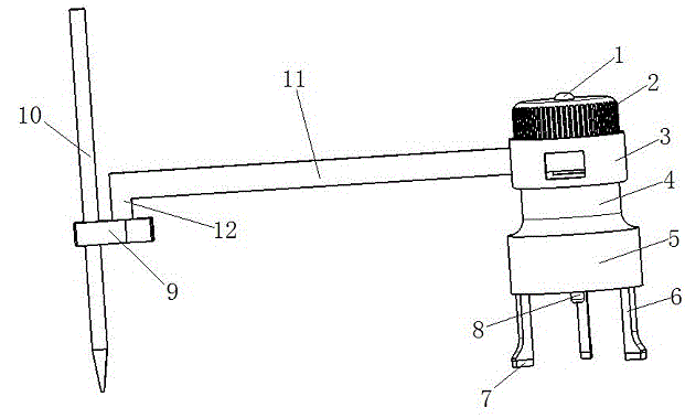
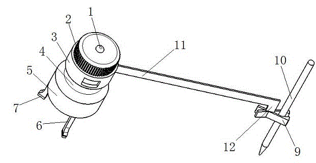
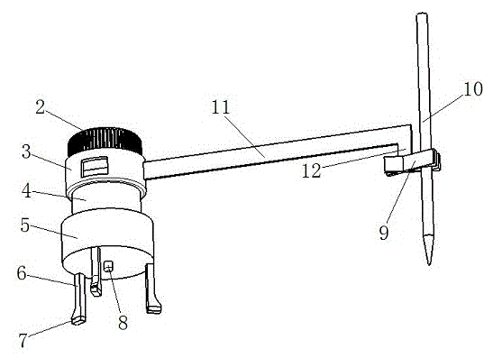
[0010] Such as figure 1 , figure 2 with image 3 Shown, the present invention is realized in this way, it comprises laser switch 1, anti-slip knob 2, transparent window 3, rotating shaft 4, base 5, tripod 6, non-slip foot pad 7, laser head 8, pen holder 9, writing The pen 10, the beam ruler 11 and the connection plate 12 are characterized in that the top of the anti-slip knob 2 is provided with a laser switch 1, the lower end of the anti-slip knob 2 is connected with the upper end of the transparent window 3, and the lower end of the transparent window 3 is connected with the upper end of the rotating shaft 4 Connected, the rotating shaft 4 is connected to the top of the base 5, the lower part of the base 5 is fixedly connected with several tripods 6, the bottom of the tripod 6 is connected with an anti-slip foot pad 7, an anti-slip knob 2, a transparent window 3, the rotating shaft 4 and the base The axes of 5 are the same, the laser head 8 is located on the axis, and is c...


PUM


Abstract

The invention discloses a laser positioning compass and belongs to stationeries. The laser positioning compass is structurally characterized in that a laser switch is arranged at the top of a non-slip knob; the lower end of the non-slip knob is connected with the upper end of a transparent window; the lower end of the transparent window is connected with the upper end of a rotary shaft; the rotary shaft is connected to the top of a base; a plurality of foot stands are fixedly connected to the lower part of the base; non-slip foot pads are connected to the bottoms of the foot stands; the non-slip knob, the transparent window, the rotary shaft and the base have the same shaft line; a laser head is positioned on the shaft line and connected onto the lower surface of the base; one end of a beam ruler is connected onto the transparent window; the other end of the beam ruler is vertically connected with a connecting plate; the lower end of the connecting plate is connected with a pen clip; and the pen clip is connected with a writing pen. The laser positioning compass is simple in structure and very convenient to use; the center of a circle can be accurately positioned by laser; the circle can be accurately drawn; a hole cannot be left in a paper sheet; the obtained drawing is beautiful; the circumferential radius can be drawn by the configured ruler; and the circle drawing efficiency is improved.

Description

technical field [0001] The invention relates to a stationery product, in particular to a laser positioning compasses. Background technique [0002] Compass is very commonly used as a tool for drawing and drawing circles. It is not only required to accurately locate the position of the center of the circle, but also to draw a circle that requires a radius. Therefore, the existing compasses generally use a pointed metal foot to locate the center of the circle, and the other supports The writing pen locates the radius of the circle. Before drawing the circle, it is necessary to measure the radius of the circle to be drawn on the ruler in advance. It is very troublesome to use, and when drawing on paper materials, because the sharp metal feet will pierce the paper, it is difficult to Potholes will be left on the smooth paper surface, which seriously affects the beauty of the drawing, and people are easily stabbed by sharp metal feet. It is not safe to use. The current compasses ...

Claims


Application Information

Patent Timeline
Patent Type & Authority Applications(China)
IPC IPC(8): B43L9/02B43L12/00
Inventor 卢晓琴高娟吴翔云张涌郭锐东
Owner EAST CHINA UNIV OF TECH
Why Eureka
Try Eureka