Control method for yarn tension of straight twisting machine

A yarn tension and control method technology, which is applied to spinning machines, continuous winding spinning machines, textiles and papermaking, etc. It can solve the problems that the outer yarn tension control cannot be accurately controlled, and the shape of the balloon cannot be optimal. , to save energy consumption and reduce noise

Active Publication Date: 2013-06-12
ZHEJIANG RIFA TEXTILE MACHINERY TECH CO LTD
View PDF5 Cites 4 Cited by
  • Summary
  • Abstract
  • Description
  • Claims
  • Application Information

AI Technical Summary

Problems solved by technology

[0003] The purpose of the present invention is to solve the problem that the hysteresis braking outer yarn tension control of the existing direct twisting machine cannot be accurately controlled a

Method used


Image

  • Control method for yarn tension of straight twisting machine

Examples


Embodiment approach 1

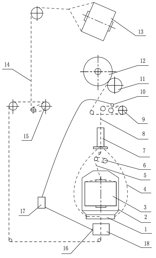
[0012] Implementation mode one: if figure 1 As shown, the direct twisting machine of the present invention includes the spindle 2 installed on the frame, the spindle drive motor 18, the leveling device 7, the overfeeding device 9, the outer yarn tensioner 15, the inner yarn tensioner 6 and the winding device, the winding device is mainly composed of a winding roller 11 and a yarn bobbin; one of the yarns is drawn from the outer yarn package 13 as the outer yarn 14, and is guided by a plurality of yarn passing wheels on the spindle twisting disc 1 and The axis of the spindle 2 is deflected in an approximately vertical direction, and is introduced into the leveler 7 through the periphery of the spindle at the edge of the twisting disc 1, and another strand of yarn is drawn out from the inner yarn package 3 in the spindle 2 as the inner yarn 5, and the same Introduced into the leveling device 7, the outer yarn 14 and the inner yarn 5 are twisted into a ply yarn 8 in the leveling ...

Embodiment approach 2

[0013] Embodiment 2: On the basis of Embodiment 1, a motor sensor 16 is set on the spindle drive motor 18 to detect any one or both of these two parameters, the motor speed and the motor current, and the motor sensor 16 is connected to the control system 17 , the control system 17 arbitrarily combines the detection results of the yarn sensor 10 and the motor sensor 16 into at least two control parameters to control the motor connected to the overfeed wheel according to the tension value of the outer yarn to meet the best form of the outer yarn balloon According to the requirements for variable speed movement, adjust the pulling speed of ply yarn.

[0014] In the above two implementations, the motor connected to the outer yarn tensioner 15 can also be controlled by the control system 17 according to different implementations with parameters such as the spindle drive motor speed, motor current, ply yarn speed, and ply yarn tension. Rotate with variable speed, drive the outer yar...


PUM


Abstract

The invention discloses a control method for yarn tension of a straight twisting machine, and belongs to the technical field of textile machinery. The problems that external yarn tension control is not accurate, and an optimum ballooning shape cannot be reached exist in the existing straight twisting machine. The straight twisting machine is characterized in that a strand yarn sensor is arranged in a yarn path between an overfeeding device and an even twisting device and used for detecting a strand yarn linear speed and tension; a motor sensor is arranged on a spindle drive motor and used for detecting a motor speed and motor current; an external yarn tensioner is driven by a separate motor to feed yarns actively; an overfeeding wheel of the overfeeding device is driven by a separate motor; and by taking one or two detection results of the two sensors as separate or combined control parameters, a control system controls a speed of the motor connected with the overfeeding wheel, adjusts a strand yarn pulling speed, and ensures that an external yarn tension value meets a requirement of the optimum yarn ballooning shape capable of allowing a wrapping angle to be minimum.

Description

technical field [0001] The invention belongs to the technical field of textile machinery, and in particular relates to a yarn tension control method of a direct twisting machine capable of saving energy consumption and reducing noise. Background technique [0002] Direct twisting machine is a kind of textile machine mainly used to directly combine two yarns into ply yarns, twist them into cords, and wind them into parallel bobbins. When combining and twisting, two strands of yarn are respectively introduced from two yarn packages, one of which is installed in the rotating spindle, and the other strand of yarn passes through the twisting disk of the spindle and passes outside the spindle , and then the two strands of yarn are merged into the twist leveler to form an inner yarn and an outer yarn, and the outer yarn will form a balloon during the rotation of the spindle. Before the yarn is introduced from the twisting disk to the balloon, the outer yarn is at least partially...

Claims


Application Information

Patent Timeline
IPC IPC(8): D01H13/10D01H1/20
Inventor 蔡国辉张超马少华
Owner ZHEJIANG RIFA TEXTILE MACHINERY TECH CO LTD
Why Eureka
Try Eureka