Hydraulic motor

A hydraulic motor and stator technology, applied in the field of hydraulic motors, can solve problems such as discharge and motor torque reduction

Inactive Publication Date: 2013-06-12
HENAN UNIV OF SCI & TECH
View PDF8 Cites 4 Cited by
  • Summary
  • Abstract
  • Description
  • Claims
  • Application Information

AI Technical Summary

Problems solved by technology

[0004] The purpose of the present invention is to provide a hydraulic motor to solve the problem that the existing hydraulic motor d

Method used


Image

  • Hydraulic motor
  • Hydraulic motor
  • Hydraulic motor

Examples


Example Embodiment

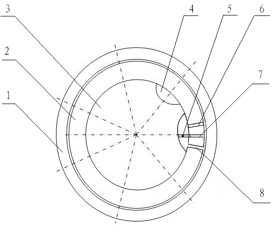
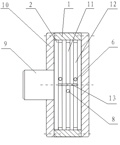
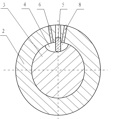
[0015] Embodiments of the hydraulic motor of the present invention: as Figure 1-3 As shown, it includes a stator and a rotor 3, the rotor 3 is rotatably assembled in the stator, the outer peripheral surface of the rotor 3 is provided with notches 4 arranged at intervals in the circumferential direction, and each notch 4 is an arc-shaped groove structure extending axially along the rotor 3, The bottom surface of each gap 4 is an arc surface like this, and each gap cooperates with the inner peripheral surface of the stator to form oil storage chambers one by one. Corresponding to each notch 4 on the inner peripheral surface of the stator, an oil injection hole 6 and an oil discharge hole 8 are opened respectively. Corresponding to each notch 4 on the surface, there are also vane grooves 13 extending in the axial direction. Radially sliding blades 5 . The bottom surface of the vane groove 13 is provided with a pressure oil hole 7. During application, high-pressure oil is injec...


PUM


Abstract

The invention discloses a hydraulic motor which comprises a stator and a rotor, wherein a gap is arranged in the outer peripheral surface of the rotor, an oil injection hole and an oil discharge hole are arranged in the inner peripheral surface of the stator, a blade slot is further arranged in the inner peripheral surface of the stator, a blade is in radial sliding fit in the blade slot, one end of the blade is in elastically abutting fit with the outer peripheral surface of the rotor, an oil storage chamber is divided into a high-pressure oil chamber and a return oil chamber by the blade, the high-pressure oil chamber and the return oil chamber are respectively communicated with the oil injection hole and the oil discharge hole which are respectively arranged at two sides of the blade correspondingly and adjacently, the oil discharge hole, the blade and the oil injection hole which are adjacent are arranged in sequence in the set rotating direction, and the peripheral span of the gap is greater than the span between the adjacent oil injection hole and the oil discharge hole. High-pressure oil in the oil storage chamber of the hydraulic oil is subjected to the circulation process from being filled to being entirely discharged out, compared with that in the starting state, the effective compression area of the high-pressure oil newly injected to the oil storage cavity is unchanged, thereby being capable of meeting the low-speed and high-load mechanical transmission requirement.

Description

technical field [0001] The invention relates to a hydraulic transmission device, in particular to a hydraulic motor. Background technique [0002] The hydraulic motor is a power device that converts the hydraulic energy provided by the hydraulic pump into mechanical energy to output rotational motion. It is mainly used in injection molding machinery, ships, hoists, etc. There are two main types of hydraulic motors, one is the vane motor, and the other is the The first is a plunger motor. Most of the traditional hydraulic motors have complex structures and large volumes, which often lead to complicated production and assembly processes. [0003] Chinese patent CN102536628A discloses a hydraulic motor, including a stator and a rotor. The rotor gap is inserted in the stator and rotates with the stator. There are four circumferentially arranged gaps on the outer peripheral surface of the rotor. The surrounding surfaces cooperate to form four oil storage cavities. There is a c...

Claims


Application Information

Patent Timeline
IPC IPC(8): F03C2/30
Inventor 杨建玺马文锁
Owner HENAN UNIV OF SCI & TECH
Why Eureka
Try Eureka