Signal connector

A signal connector and signal technology, applied in the field of data transmission, can solve the problem of general shielding effect and achieve the effect of reducing signal crosstalk

Active Publication Date: 2013-06-12
HUAWEI MACHINERY
View PDF3 Cites 44 Cited by
  • Summary
  • Abstract
  • Description
  • Claims
  • Application Information

AI Technical Summary

Problems solved by technology

However, the shielding effect of this technical solution using a single shielding sheet is average, and it is usually only suitable for systems with a transmission rate lower than 10Gbps. For the transmis

Method used


Image

  • Signal connector
  • Signal connector
  • Signal connector

Examples


Embodiment Construction

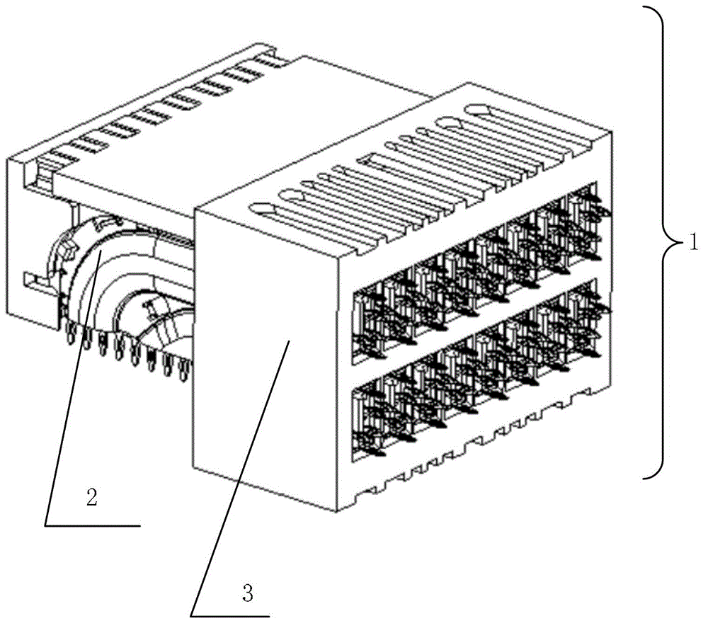
[0030] figure 1 A schematic diagram of a signal connector provided by an embodiment of the present invention. Such as figure 1 As shown, the signal connector 1 is formed by mating a first socket 2 and a second socket 3 .

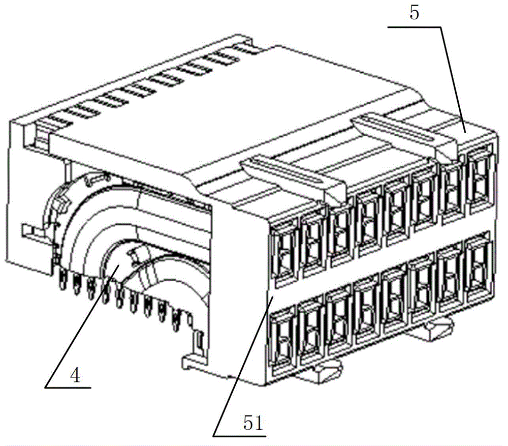
[0031] figure 2 It is a schematic diagram of the first connector provided by the embodiment of the present invention. As shown in the figure, the first connector 2 includes: a signal transmission unit 4 and a first mating fixed end 5 . The first mating fixed end 5 has a first insertion surface 51 , and the signal transmission unit 4 is inserted on the first insertion surface 51 of the first mating fixed end 5 .

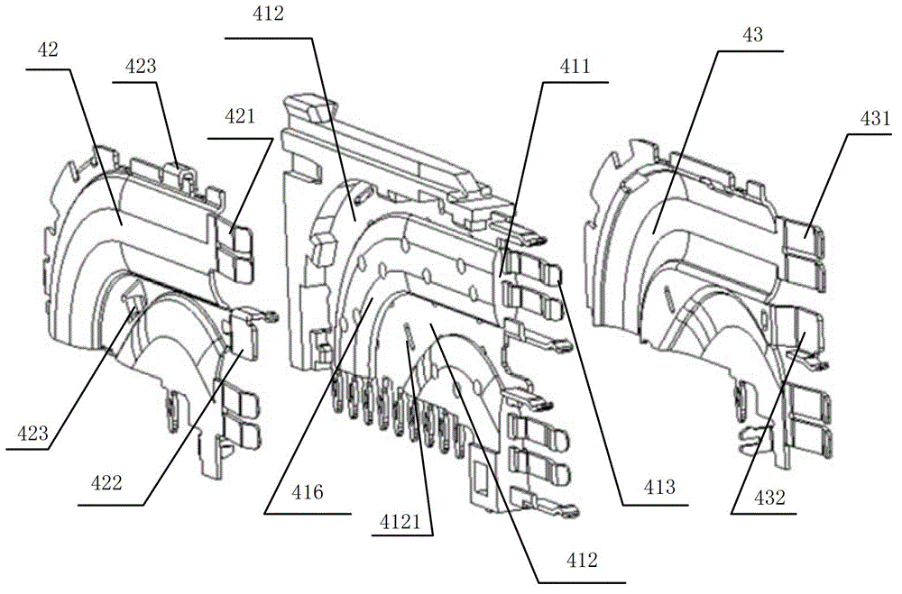
[0032] image 3 The expanded view of the signal transmission unit provided by the embodiment of the present invention. The signal transmission unit 4 includes: a signal transmission part 41 , a first shielding part 42 and a second shielding part 43 . The first shielding component 42 and the second shielding component 43 cover the two sides o...


PUM

PropertyMeasurementUnit
Input resistanceaaaaaaaaaa

Abstract

The embodiment of the invention discloses a signal connector. The signal connector comprises a first plug-in connector and a second plug-in connector, wherein the first plug-in connector comprises a signal transmission unit comprising a signal transmission part, a first shielding component and a second shielding component, and a first matched fixing end for containing the signal transmission unit; the second plug-in connector comprises a second matched fixing end for containing a second signal terminal pair and a third shielding component; and when the first plug-in connector is in plug-in connection with the second plug-in connector, a first signal terminal pair and the second signal terminal pair are arranged in a connection way, the third shielding component and a first clamping joint of the signal transmission unit are arranged in a clamping way, the third shielding component is connected with the first shielding component and the second shielding component in a clamping way so as to form an O-shaped shielding cavity structure coating the first signal terminal pair and the second signal terminal pair, and the O-shaped shielding cavity structure is used for shielding the signals transmitted by the first signal terminal pair and the second signal terminal pair. By the embodiment, the signal crosstalk problem of the signal connector in a high-speed system can be solved.

Description

technical field [0001] The invention relates to the technical field of data transmission, in particular to a signal connector used in a high-speed signal transmission system. Background technique [0002] In the field of data transmission, the signal transmission speed of communication equipment is getting faster and faster. In high-speed systems, connectors for differential signals are usually used, and when high-speed signals pass through the connectors, the crosstalk between signals will be relatively large, so signal isolation is required. At present, for high-speed signals with a rate exceeding 3 Gbps, a metal shielding sheet is usually used to shield the signal lines. However, the shielding effect of this technical solution using a single shielding sheet is average, and it is usually only suitable for systems with a transmission rate lower than 10Gbps. For the transmission of higher-speed signals, such as high-speed systems with a transmission rate of 25Gbps or even 5...

Claims


Application Information

Patent Timeline
IPC IPC(8): H01R13/6581
Inventor 肖聪图汪泽文王云
Owner HUAWEI MACHINERY
Why Eureka
Try Eureka