Spring-loaded pressure relief device

A technology of releasing device and pressure, applied in the field of pressure releasing device, which can solve the problems of secondary damage in the discharge area, uneven distribution of discharge materials, etc.

Inactive Publication Date: 2015-11-25
AMT INT INC
View PDF12 Cites 0 Cited by
  • Summary
  • Abstract
  • Description
  • Claims
  • Application Information

AI Technical Summary

Problems solved by technology

However, when the hinged portion of the tray is raised at an angle to relieve the pressure differential, the overpressured vapor is discharged in a directional manner determined by the position of the hinge and the resulting angle of the hinged portion of the tray, thereby Uneven distribution of discharge material and thus possible secondary damage to the discharge area (e.g. the tray directly above the discharge tray)

Method used


Image

  • Spring-loaded pressure relief device
  • Spring-loaded pressure relief device
  • Spring-loaded pressure relief device

Examples


Embodiment Construction

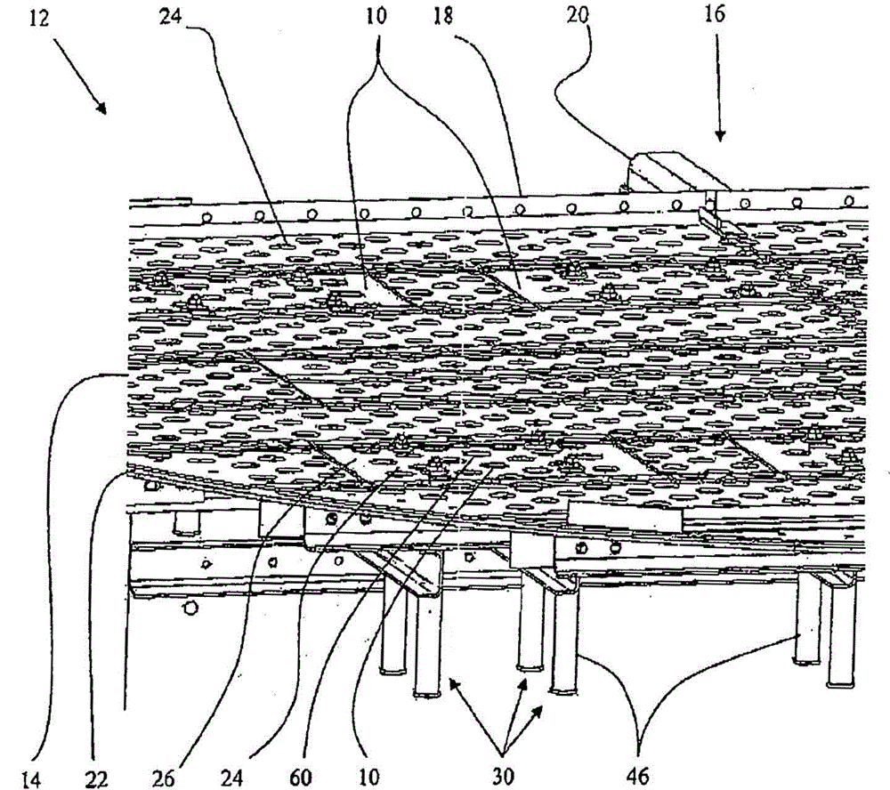
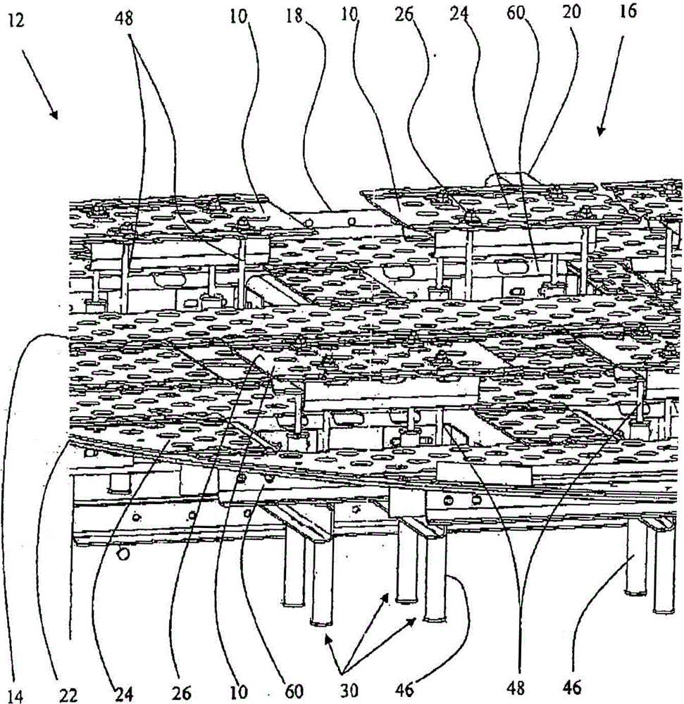
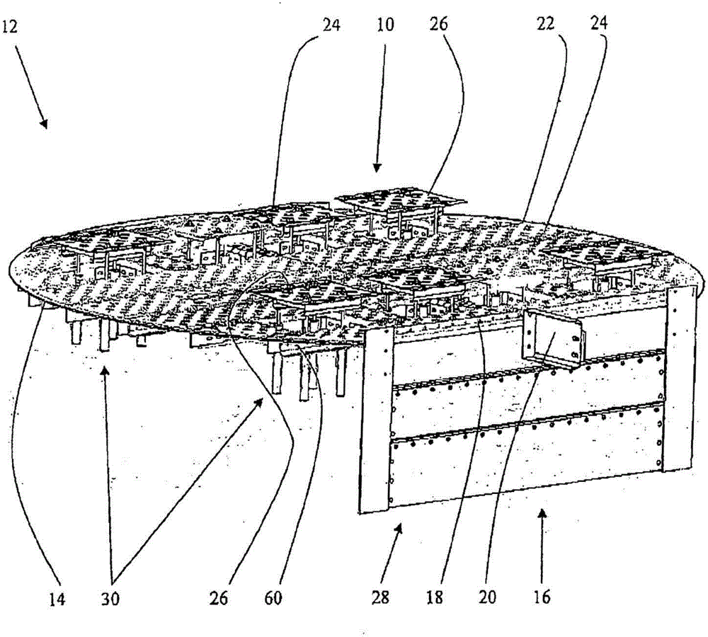
[0022] refer to Figure 1-3 , a tray assembly 12 for vapor / liquid contact is installed in a distillation column with side walls (not shown). The outer edges of the tray assembly 12 are attached to the side walls. Tray 12 has a deck 14 which may comprise one or more sections and at least one downcomer 16 . The deck 14 has perforations 24 through which vapors can rise. Those skilled in the art will appreciate that the perforations 24 may be simple holes or include valves, blisters or other devices to control and distribute the vapor rising through the perforations 24 . Typically, tray 12 has an outlet weir 18 to maintain liquid and froth depth above deck 14 . Additional structural components may also be included to maintain the integrity and position of the trays 12 within the distillation column, for example, structural components 20 ( Figure 1-Figure 3 ) extends through the downcomer 16, from the tray 12 above the downcomer wall 28 to the inner surface of the column wall....


PUM


Abstract

A pressure relief device for preventing damage to a tray in a distillation column arising from sudden pressure surges includes a plate normally closing an opening in the tray, a frame above which the tray can move vertically, and at least one spring assembly connecting the plate to the frame. When there is a pressure surge, the plate moves vertically to open the pressure relief device. When the pressure differential between zones above and below the plate has been relieved, the spring assembly returns the pressure relief device to the closed position in which the plate is coplanar with the fixed tray.

Description

technical field [0001] The present invention relates to a pressure relief device for distillation column trays in chemical process columns. technical background [0002] Various designs of trays used in distillation columns (also called columns) are known. In each design, trays are located within the column for vapor and liquid contact between the components of the mixture. For example, detailed tray designs are found in "Equilibrium Staged Separations" by Philip C. Wankat and published by Elsevier (1988), "Separation Processes" by C. Judson King and published by McGraw-Hill Book Company (2nd Edition, 1980), Performed in "Distillation Design" by Henry Z. Kister and published by McGraw-Hill, Inc. (1992) and "Distillation: Principles and Practice" by Johann G. Stichlmair and James R. Fair and published by Wiley-VCH (1998) described. [0003] Distillation columns are designed to perform a variety of separation processes as described in commercial literature available from di...

Claims


Application Information

Patent Timeline
Patent Type & Authority Patents(China)
IPC IPC(8): B01D3/32
CPCB01D3/42B01D3/22B01D3/324B01D3/326B01D3/32
Inventor 法扎德·G·塔哈马西拉里·W·伯顿沛雨·波莉·蒋
Owner AMT INT INC
Why Eureka
Try Eureka