
Perpetual motion fan module

a technology of permanent motion and fan module, which is applied in the direction of mechanical equipment, machines/engines, transportation and packaging, etc., can solve the problems of system failure, system failure, and failure to work continuously, so as to save steady amps

Inactive Publication Date: 2005-07-14
BAILEY RUDOLPH V
View PDF3 Cites 3 Cited by
  • Summary
  • Abstract
  • Description
  • Claims
  • Application Information

AI Technical Summary

Benefits of technology

"The present invention is about a battery-operated fan module that uses re-cycling of energy to offset energy loss and increase the amount of energy available for use. The invention includes a system of re-cycling the energy molecule splitter and comptroller, which facilitates perpetual motion of the fan module. The invention solves the problem of friction and allows for the machine to continue operating even with no other external energy source. The invention also includes a computer with touch monitor and remote communicator / controller. The speed shaft and torque ratio must be carefully calculated to ensure the machine operates at the optimal speed. The invention can be used in various applications, such as for the comfort of human kind or animals, and is more efficient and cost-effective than other similar products."

Problems solved by technology

However all of these attempts fall short of their intended purposes, as they have other limitations.
In a situation where no electrical outlet is available their systems would not work.
However the Sun does not always shine, so that system cannot always be relied on for continuous use.
Additionally, the prior patents and commercial techniques do not suggest the present inventive combination of component eliminates arraigned and configured as disclosed herein.
We found it necessary to simplify this application due to the complexity and controversy of the subject matter.
Polyp chain is much quieter and offers less friction, and it is our choice, but it is very expensive compared to chain and sprocket, We recommend this over belt and pulley drive, because they give little or no slippage with less belt tension.

Method used


Image

  • Perpetual motion fan module
  • Perpetual motion fan module

Examples


Embodiment Construction

Description

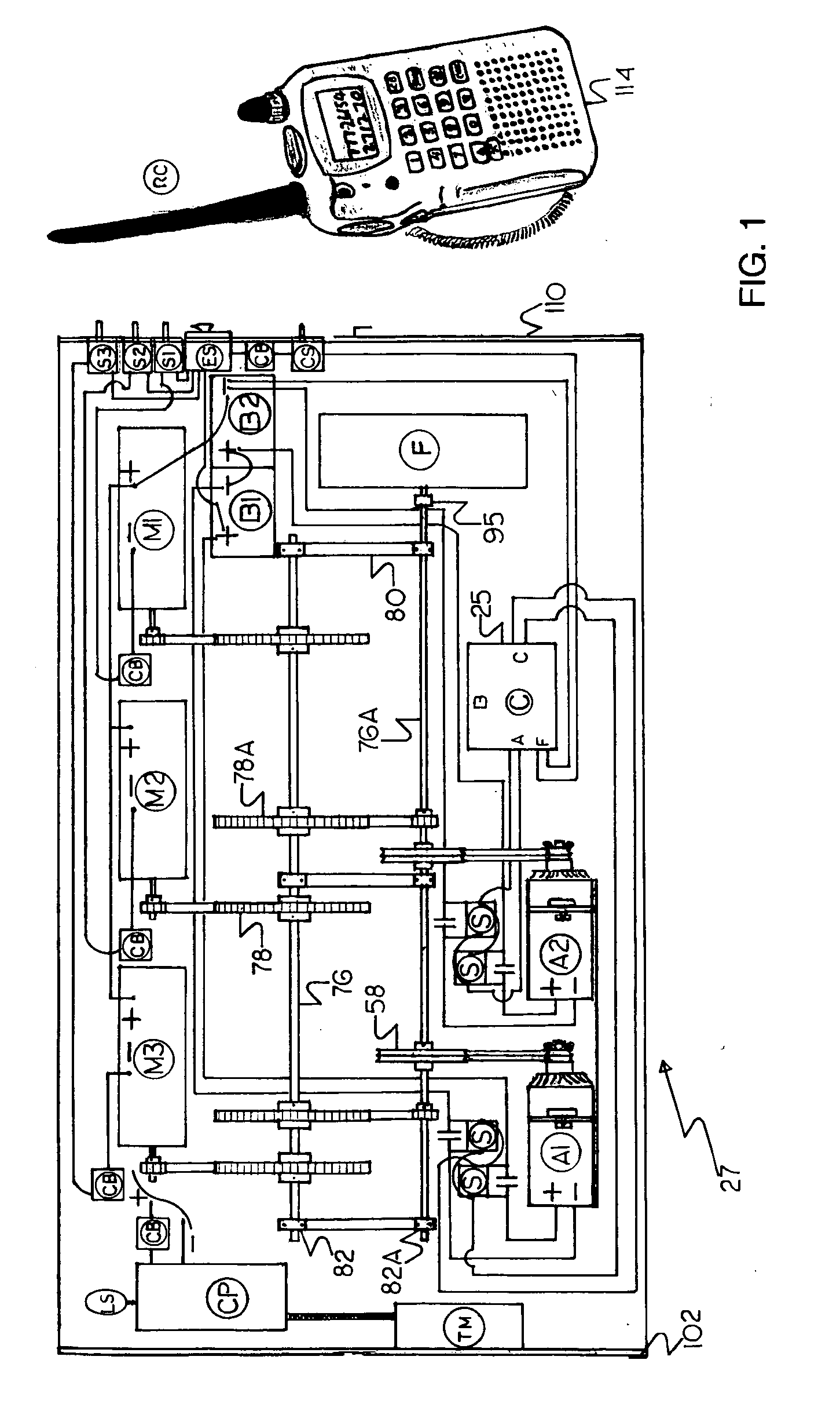
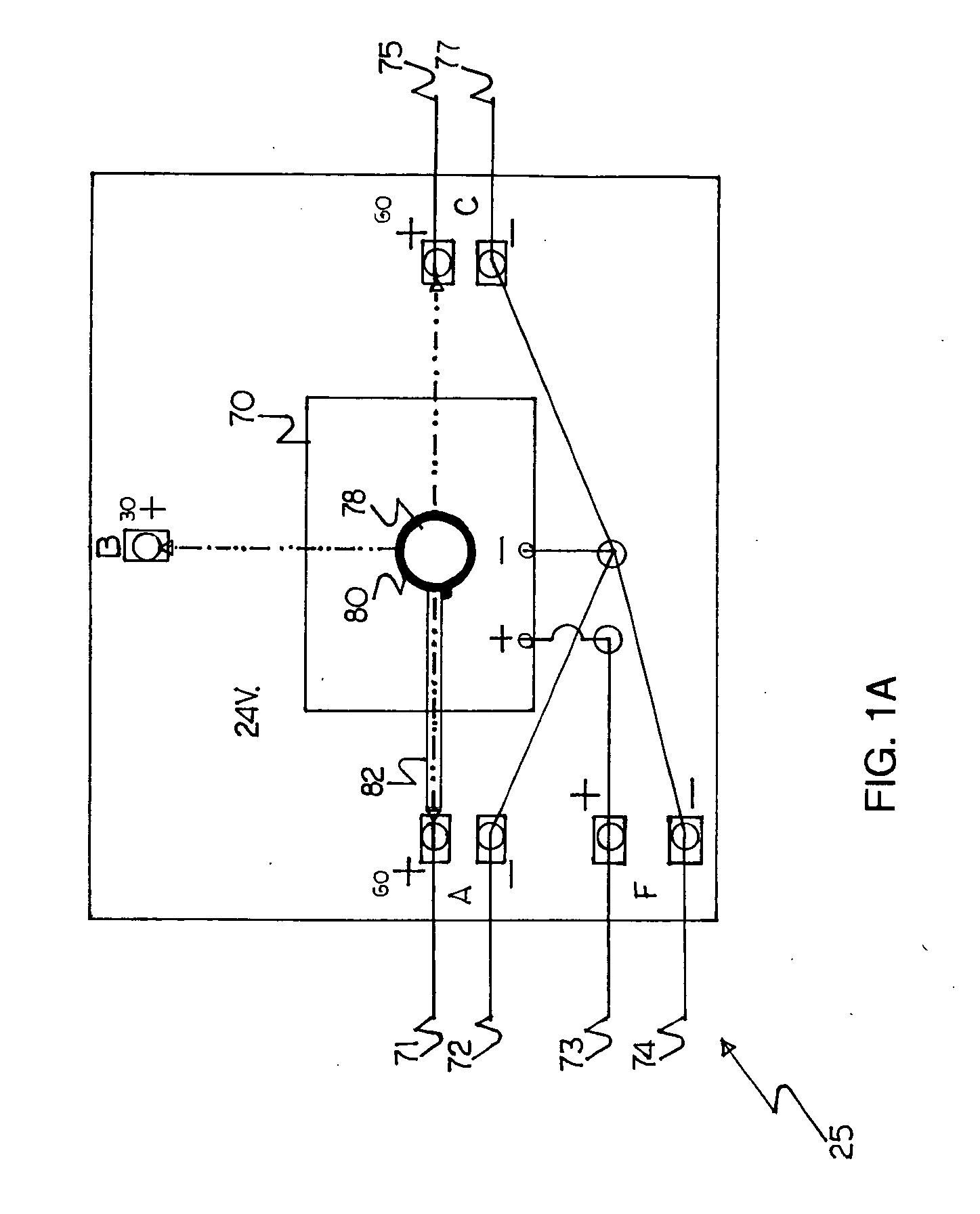
[0030] Referring now to the drawing and, in particular, to FIG. 1 wherein there is illustrated a typical embodiment of a perpetual motion fan module 27. The present version of the invention 27 is constructed of a wooden enclosure cabinet, or other non-conductive material such as plastic, fiber glass, or any other such like material, or a combination thereof. The cabinet should have a removable top cover, and a front access door 110, and a rear access door 102. The doors should have vent louvers to permit venting of moving parts. The base should be made sturdy enough to support the weight of all component parts. Swivel caster wheels can also be installed for easy movement of module. Lifting lugs can be installed to allow for mechanical lifting devices to be used in moving module. The base should be constructed to allow for a forklift to get under it. The invention 27 consist of three 24 volt one horse power motors (M1, M2, M3,) or any other suitable ratings. Included als...


PUM


Abstract

A means for creating perpetual motion of a battery operated device has been disclosed. A battery operated device such as a large commercial fan can be made to operate continuously eliminating the need for a separate re-charging process for the batteries as long as the fan is kept in operation. This can be accomplished having at least two batteries which are connected in series to give the desired volts, and at least two charging components to charge each battery separately, as the fan is used.

Description

DESCRIPTION OF RELATED APPLICATIONS [0001] This application is a continuation of CO-pending application Ser. No. 10 / 811,382 Filed on Mar. 27, 2004, which was a continuation of application Ser. No. 10 / 075,569 Filed on Feb. 13, 2002, which claimed benefit of 60 / 303,871 filed on Jul. 9, 2001, and also claimed benefit of 60 / 349,731 filed on Jan. 17, 2002. This Application is also a Continuation-in-part of CO-pending Application Serial No. U.S.60 / 644,725 Filed on Jan. 18, 2005.BACKGROUND OF THE INVENTION [0002] This version of the invention is concerned with the field of battery operated devices, which employs a system of re-charging the batteries while the device is used, therefore allowing the devices to operate continuously. [0003] 1. Prior Art [0004] A variety of battery operated devices are on the market, which uses re-chargeable batteries, but all posses common limitations, which are as following: Their duration of operation is limited to the extent that batteries must to be re-cha...

Claims


Application Information

Patent Timeline
Patent Type & Authority Applications(United States)
IPC IPC(8): H02K53/00
CPCF03G7/08H02K53/00F03G7/10F03G7/122
Inventor BAILEY, RUDOLPH V.
Owner BAILEY RUDOLPH V
Learn More