Die clamping device for injection molding machine

A technology of injection molding machine and mold clamping device, which is applied in the field of connection mechanism, and can solve problems such as inability to completely absorb deformation and damage

Active Publication Date: 2013-06-12
MITSUBISHI HEAVY INDS PLASTIC TECH
View PDF7 Cites 3 Cited by
  • Summary
  • Abstract
  • Description
  • Claims
  • Application Information

AI Technical Summary

Problems solved by technology

[0006] When the inclination of the movable mold table 3 caused by the wear of the side guide plate 13 and the deformation of the fixed mold table 2 and the movable mold table 3 caused by the increase of the mold clamping force occur, even if the movable mold table moving mechanism 40 and The connecting mechanism of the supporting member 60 fixedly installed on the movable mold plate 3 uses the pressing member 61 and the front end 45 of the working rod 42 of the actuator 41, and only passing through the gaps S1 and S2 between the pressing member 61 and the front end 45 is also sufficient. Cannot completely absorb the wear of the side guide plate 13 of the movable die plate 3, the inclination of the movable die plate 3 and the deformation of the fixed die plate 2 and the movable die plate 3
As a result, the working rod 42 of the actuator 41 is deformed at the connecting portion ( Figure 18 As shown in X2), it will cause damage as it is repeatedly bent

Method used


Image

  • Die clamping device for injection molding machine
  • Die clamping device for injection molding machine
  • Die clamping device for injection molding machine

Examples


no. 1 approach ]

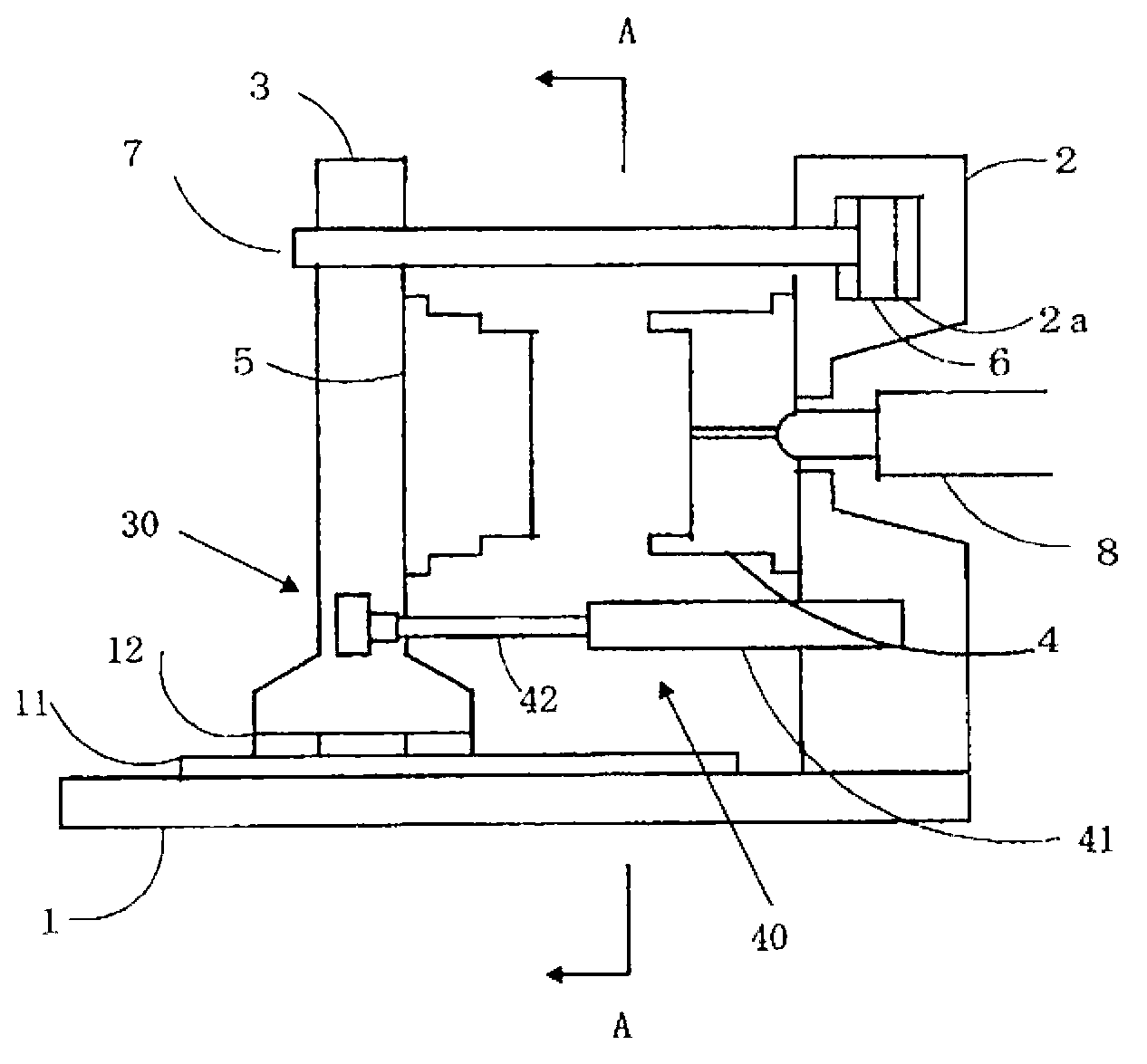
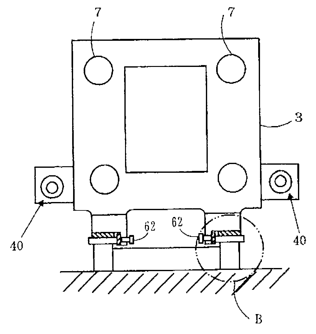
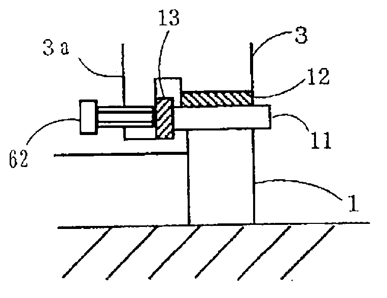
[0093] The first embodiment will be described based on the drawings. figure 1 is a side view of the injection molding device of the present invention; figure 2 yes figure 1 The A-A profile; image 3 yes figure 2 Enlarged view of Part B of ; Figure 4 yes means figure 1 The top view of the mold plate and the mold plate opening and closing mechanism of the injection molding device (the double dotted line indicates the movable mold plate when the mold is opened); Figure 5 yes Figure 4 The detailed drawing of the mold plate and the joint part C of the mold plate opening and closing mechanism; Image 6 yes means Figure 4 The tilted top view of the movable die plate when the side guide plate has been asymmetrically worn; Figure 7 yes Image 6 Enlarged view of Part E of (Part 1); Figure 8 yes Image 6 Enlarged view of Part E of (Part 2); Figure 9 is expressed in Figure 4 The enlarged view of the front end position of the hydraulic piston rod at the joint part...


PUM


Abstract

Breakage of the actuator moving the movable platen in the clamping device of an injection moulder is prevented. The clamping device includes a movable platen shifting device increasing and decreasing a horizontal distance between the movable platen (3) and the fixed platen (2). It includes an actuator (41), a clevis pin connecting the actuator (41) and the movable platen (3), a clevis pin holding part holding a central axis of the clevis pin perpendicular to a moving direction of the movable platen (3), and a clevis pin connecting part that connects the actuator (41) and the clevis in. The clevis pin connecting part is a supporting structure rotating with the clevis pin. The clevis pin connecting part is supported by the movable platen (3). The clevis pin, the clevis pin connecting part, and the front end of the actuator are aligned in a straight line.

Description

technical field [0001] The invention relates to a mold plate opening and closing device of an injection molding machine, in particular to a connecting mechanism between a working end of an actuator that drives a movable mold plate forward and backward and the movable mold plate. [0002] This application claims priority based on Japanese Patent Application No. 2011-007135 for which it applied in Japan on January 17, 2011, and uses the content here. Background technique [0003] Currently, as described in Patent Document 1 and Patent Document 2, in the mold plate opening and closing mechanism of an injection molding machine, hydraulic or electric actuators are directly fixed to the movable mold plate and the fixed mold plate. or, as in Figure 16 , Figure 17 As shown, the connection between the movable die plate and the actuator consists of the pressing member 61 installed on the movable die plate 3 and the working rod 42 of the actuator 41 provided with the groove portion ...

Claims


Application Information

Patent Timeline
Patent Type & Authority Applications(China)
IPC IPC(8): B29C45/64
CPCB29C45/64B29C45/1761B29C45/03
Inventor 藤田三郎加藤直纪
Owner MITSUBISHI HEAVY INDS PLASTIC TECH
Why Eureka
Try Eureka