Printer and method for replacing plate cylinder thereof

A printing plate cylinder and printing device technology, which is applied to printing, printing machines, rotary printing machines, etc., and can solve problems such as cumbersome operations

Active Publication Date: 2013-06-19
FUJI KIKAI IND
View PDF10 Cites 7 Cited by
  • Summary
  • Abstract
  • Description
  • Claims
  • Application Information

AI Technical Summary

Problems solved by technology

[0005] However, according to the content of the invention disclosed in Patent Document 1, after the printing plate cylinder is installed on the unit fixed side of the printing unit, it is not known that the mark that becomes the reference p

Method used


Image

  • Printer and method for replacing plate cylinder thereof
  • Printer and method for replacing plate cylinder thereof
  • Printer and method for replacing plate cylinder thereof

Examples


no. 1 approach )

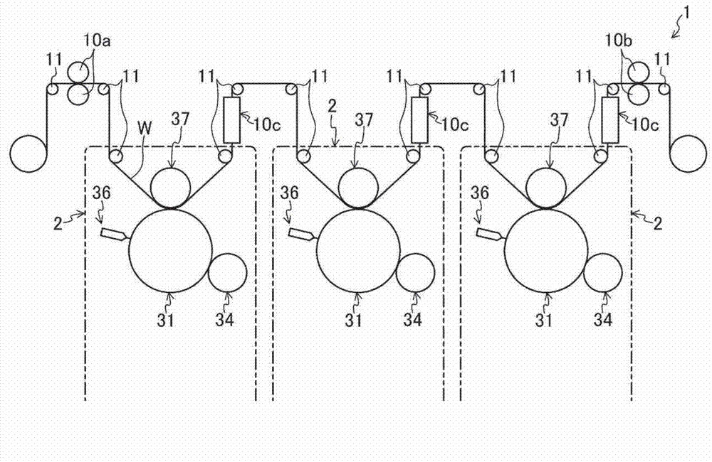
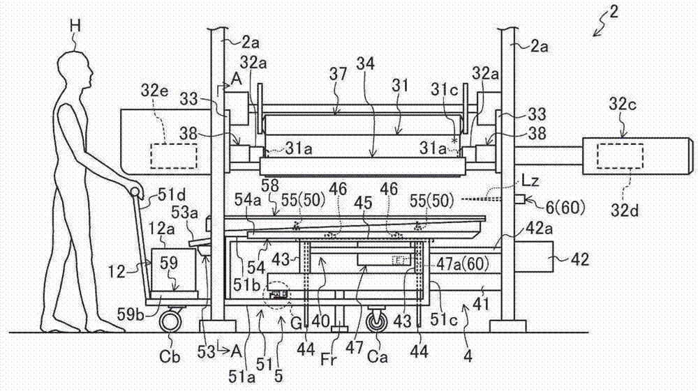
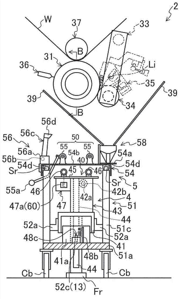
[0085] figure 1 The printing device 1 according to the first embodiment of the present invention is shown. This printing device 1 includes: a printing unit 2 that supports a printing plate cylinder 31 that transfers ink or the like to a substrate W such as a plastic film and allows the printing plate cylinder 31 to rotate; The bottom of the unit 2 or the cart 5 that is moved out from the bottom of the printing unit 2 (refer to figure 2 and image 3 ). There are three printing units 2 arranged side by side.

[0086] exist figure 1 The upper left side of the paper surface is provided with a delivery roller 10a that sends out the printed material W. On the other hand, on the figure 1 A winding roller 10b for winding up the substrate W is provided on the upper right side of the paper. A plurality of guide rollers 11 are provided between the delivery roller 10a and the take-up roller 10b, and the printed material W is wound on each of the guide rollers 11 and conveyed while ...

no. 2 approach )

[0220] Figure 20 A printing device 1 according to a second embodiment of the present invention is shown. The difference between this second embodiment and the first embodiment is only as follows: the printing unit 2 is one, and when the printing plate cylinder 31 is replaced, the printing plate cylinder 31 is supported by the two vertical frames 2a to be able to rotate, and then The registration mark 31c is positioned relative to the substrate W and printing is started. Other points are the same as the first embodiment. Therefore, the detailed description will be omitted below.

[0221] Therefore, according to the second embodiment of the present invention, even if there is only one printing unit 2, it is possible to know in advance what is required to position the printing plate cylinder 31 in the state where the printing plate cylinder 31 has been loaded on the cart 5. For the position data of the registration mark 31c, the time spent from pushing the trolley 5 to the pr...


PUM


Abstract

The invention discloses a printer and a method for replacing a plate cylinder thereof. The plate cylinder (31) comprises a key groove (31b) and a registration mark (31c). The plate cylinder (31) is moved above or off from a printing unit (2) by a cart (5). The printing unit (2) comprises a plate cylinder hand-over mechanism (4), by which the plate cylinder (31) is handed over between two vertical frames (2a) and the cart (5), and a key groove position detection mechanism (60) for detecting the position of the key groove (31b). The cart (5) is provided with a plate cylinder rotation part (50) which enables the plate cylinder (31) to rotate around an axle center so that the registration mark (31c) can be positioned at a pre-determined position. The angle of the key groove (31b) and the registration mark (31c) around the axle center can be calculated by a control panel (7). Accordingly, the stopping time of the printer when the plate cylinder is replaced can be shortened, and the efficiency can be bettered.

Description

technical field [0001] The invention relates to a printing device and a method for replacing a plate cylinder thereof. The printing device includes a printing unit having a rotatable printing cylinder supported by the printing device by attaching The ink on the substrate is transferred to the substrate for printing. Background technique [0002] So far, in the general printing device, in the state where the rotatable printing plate cylinder supported on the printing unit is positioned relative to the substrate (hereinafter referred to as mark positioning), the printing plate cylinder attached to the outer peripheral surface of the printing plate cylinder is rotated. The ink on it is transferred to the substrate for printing. [0003] The above-mentioned printing plate cylinder is provided with a keyway for insertion of a key on the fixed side of the printing unit, and when the printing plate cylinder is replaced, the printing plate is aligned by inserting the key into the k...

Claims


Application Information

Patent Timeline
IPC IPC(8): B41F27/00B41F13/12
CPCB41F9/18B41F13/24B41F33/08B41F33/14
Inventor 山本弘国竹高明
Owner FUJI KIKAI IND
Why Eureka
Try Eureka