
Wind deflector

A technology for windshields and tensioning devices, applied in transportation and packaging, roofs, vehicle parts, etc., can solve problems such as discomfort, bending of windshields, wind noise, etc., to reduce wind noise and roaring noise, reduce Effects of wind noise and roar noise

Inactive Publication Date: 2013-06-19
GM GLOBAL TECH OPERATIONS LLC
View PDF6 Cites 2 Cited by
  • Summary
  • Abstract
  • Description
  • Claims
  • Application Information

AI Technical Summary

Problems solved by technology

[0004] The known wind deflector exhibits the disadvantage that, in the active position of the wind deflector, the lower second edge is spaced from the edge of the sliding sunroof, and the wind deflector can bend due to the oncoming wind
The resulting gap causes wind and growl noises, which can be perceived as uncomfortable, especially at high speeds

Method used


Image

  • Wind deflector
  • Wind deflector
  • Wind deflector

Examples


Embodiment Construction

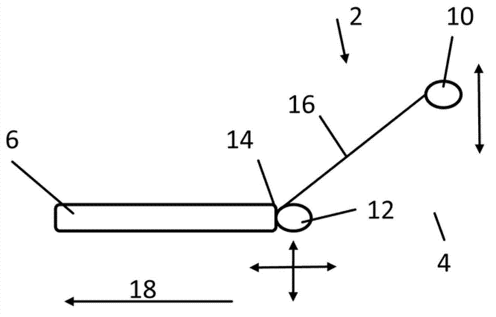
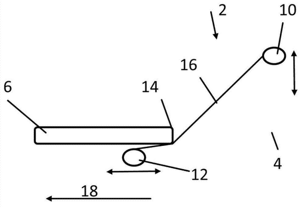
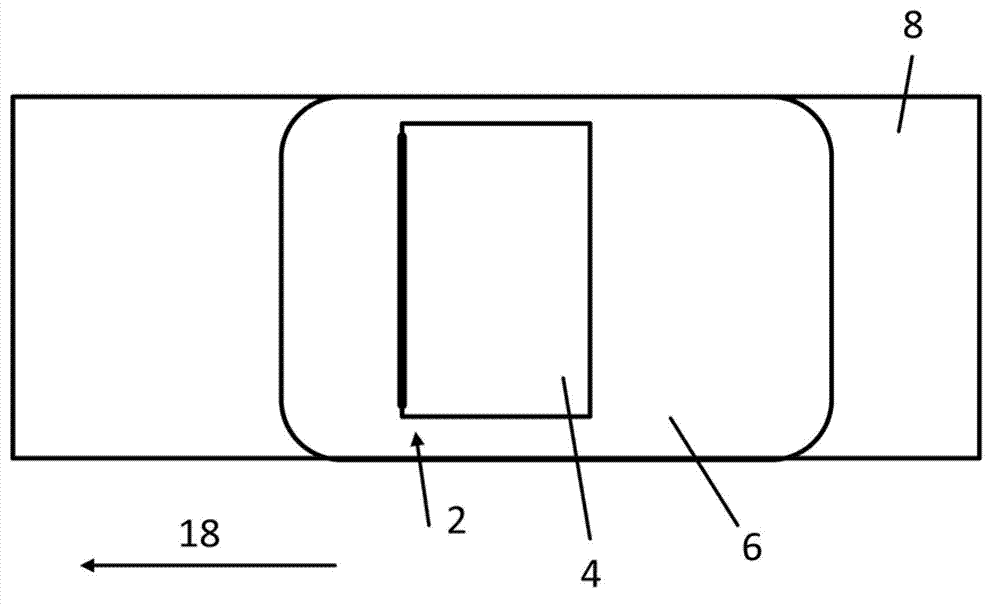
[0033] The drawing shows a wind deflector generally designated 2 . The wind deflector 2 is attached to an opening 4 of a wall part 6 of the motor vehicle 8 through which wind, in particular headwind, can escape.

[0034] The wind deflector 2 is shown in the drawing in an active position facing the wind, in which a first displaceable tensioning arm 10 protrudes from the opening 4 above the wall part 6 . exist figure 1 In the exemplary embodiment shown, the second displaceable tensioning arm 12 bears against the edge 14 of the opening 4 of the wall part 6 .

[0035] The edge of the overflowable opening 4 and the first tensioning arm 10 and the second tensioning arm 12 extend transversely to the longitudinal direction 18 of the motor vehicle 8 .

[0036] Arranged between the first tensioning arm 10 and the second tensioning arm 12 is a planar wind deflector 16 stretched by the first tensioning arm 10 and the second tensioning arm 12 . In particular, the wind deflector 16 is te...


PUM


Abstract

The invention relates to a wind deflector 2 for an opening 4 in a wall-like element such as a roof 6 of a motor vehicle (8 see fig 3) over which air flows. The deflector 2 can be moved from a basic position with negligible flow exposure into an exposed operating position, with a movable first clamping arm 10 that protrudes over the wall element 6 in the exposed operating position, with a movable second clamping arm 12, and with wind deflecting means 16 extending between the clamping arms 10, 12. The second clamping arm 12 and / or the wind deflecting means 16 substantially abuts or lies against an edge 14 of the opening 4 in an operating position.

Description

technical field [0001] The invention relates to a wind deflector for a floodable opening in a panel part of a motor vehicle and to a motor vehicle with such a wind deflector. Background technique [0002] Wind deflectors are known on motor vehicles with sliding sunroofs. The wind deflector is positioned within the vehicle interior when the sliding sunroof is in the closed position, and protrudes at least partially from the roof when the sliding sunroof is in the open position. Here, the wind deflector is in its active position, in which it blocks or deflects the oncoming wind. [0003] A wind deflector is known from DE 195 18 696 A1, in which a first edge of the wind deflector is displaced upwards, whereas a second edge is fixedly seated on the sunroof opening. A wind deflector is arranged between the two flanges and is blown against by the wind in the active position. [0004] The known wind deflector exhibits the disadvantage that, in the active position of the wind def...

Claims


Application Information

Patent Timeline
IPC IPC(8): B60J7/22
CPCB60J7/22
Inventor A.博伊威特I.费蒂尔M.廷尼斯K-D.克雷默
Owner GM GLOBAL TECH OPERATIONS LLC
Features
  • Generate Ideas
  • Intellectual Property
  • Life Sciences
  • Materials
  • Tech Scout
  • Unparalleled Data Quality
  • Higher Quality Content
  • 60% Fewer Hallucinations
Learn More