
Pressure regulating mechanism capable of setting initial pressure

A pressure regulating mechanism and pressure technology, applied in mechanical equipment, fluid flow and other directions, to achieve the effect of low processing difficulty, simple structure and stable pressure regulation

Active Publication Date: 2015-06-03
ZHEJIANG UNIV OF TECH
View PDF6 Cites 0 Cited by
  • Summary
  • Abstract
  • Description
  • Claims
  • Application Information

AI Technical Summary

Problems solved by technology

In order to ensure that the reversing main valve is reset in place in the existing pressure regulating mechanism, the spring needs to have a certain amount of pre-compression, and the pilot proportional pressure reducing valve is generally adjusted from zero pressure. The range of precompression is empty stroke

Method used


Image

  • Pressure regulating mechanism capable of setting initial pressure
  • Pressure regulating mechanism capable of setting initial pressure
  • Pressure regulating mechanism capable of setting initial pressure

Examples


Embodiment 1

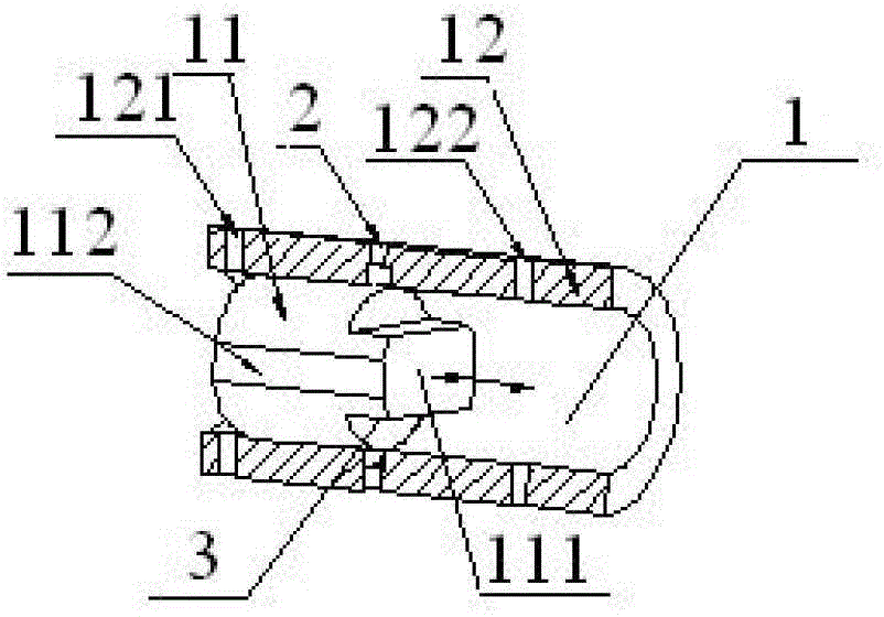
[0025] Embodiment 1 The initial pressure regulating mechanism that can be set according to the present invention includes a fluid laminar flow realization mechanism 1, a pressure taking point 2 and a pressure taking point position regulating mechanism 3;

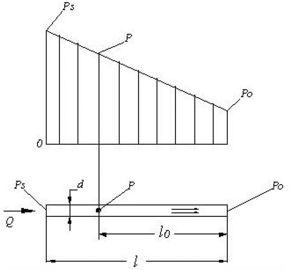
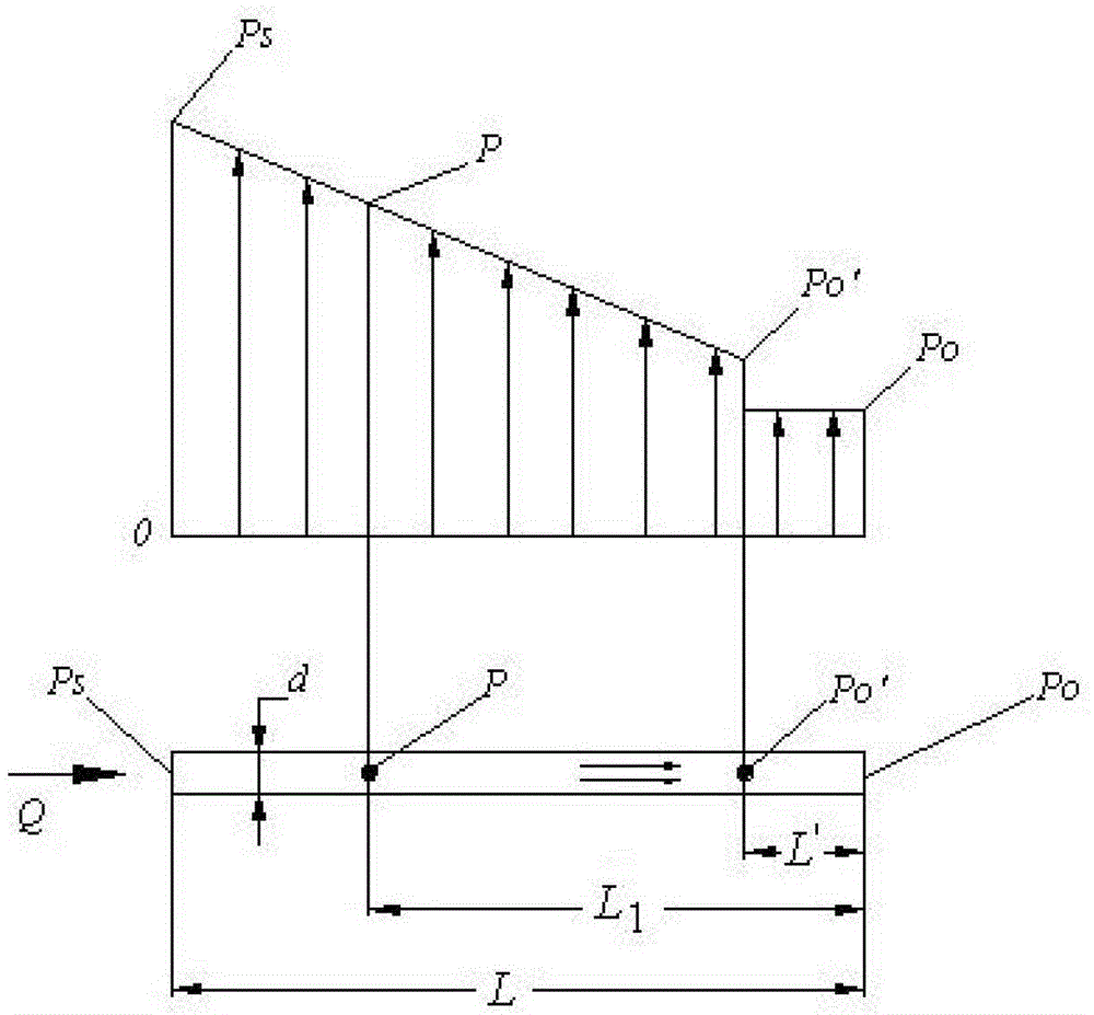
[0026] The fluid laminar flow realization mechanism 1 includes a valve core 11 and a valve sleeve 12. The end surface of the valve core 11 facing the oil outlet 122 is provided with a boss 111; the side wall of the valve core 11 is axially provided with a through groove 112, and the through groove 112 extends to the front end of the boss 111; the gap 13 between the through groove 112 of the valve core 11 and the valve sleeve 12 communicates with the oil inlet 121 and the oil outlet 122, and the gap is Laminar laminar flow channel, the fluid flow in the gap 13 presents a laminar flow state, and the pressure distribution of the oil inlet 121 and the oil outlet 122 presents a stable linear distribution;

[0027] The pressure-ta...


PUM


Abstract

A pressure regulating mechanism capable of setting an initial pressure comprises a fluid layer flow achieving mechanism, a pressure measuring point and a pressure measuring point position regulating mechanism. The fluid layer flow achieving mechanism comprises a valve core and a valve sleeve. A boss is arranged on an end face, towards one side of an oil outlet, of the valve core. A through groove is formed in the side wall of the valve core in the axial direction, and extends to the front end of the boss. A gap of the through groove of the valve core and the valve sleeve is communicated with an oil inlet and the oil outlet. Fluid in the gap is in a layer flow flowing state in a flowing mode. Pressure distribution of the oil inlet and the oil outlet is in a stable linear distribution. The pressure measuring point is a pressure measuring hole penetrating through the valve sleeve. The pressure measuring hole is communicated with the hole. The pressure measuring point position regulating mechanism comprises the valve core and a pushing component which pushes the valve core to move in the valve sleeve. The length of the boss can be regulated according to the actual needs and the initial pressure of the pressure regulating mechanism can also be set according to actual needs, pressure regulating is stable, control sensitivity is high, and processing difficulty is low.

Description

technical field [0001] The invention relates to a pressure regulating mechanism capable of setting initial pressure. Background technique [0002] Proportional pressure control valves are often used as pilot valves to form two-stage or three-stage valves. For example, the electro-hydraulic proportional reversing valve is composed of an electromagnetic force motor, a proportional pressure reducing valve and a hydraulic directional valve. Balance, so as to control the displacement opening of the reversing main valve. In order to ensure that the reversing main valve is reset in place in the existing pressure regulating mechanism, the spring needs to have a certain amount of pre-compression, and the pilot proportional pressure reducing valve is generally adjusted from zero pressure. The range of pre-compression is empty stroke. Contents of the invention [0003] In order to solve the problem of an idle stroke in the current pressure regulating mechanisms, the present invent...

Claims


Application Information

Patent Timeline
Patent Type & Authority Patents(China)
IPC IPC(8): F15D1/02
Inventor 裴翔
Owner ZHEJIANG UNIV OF TECH
Learn More