
Hydraulic artificial muscle hydraulic drive and control system

A technology of artificial muscle and control system, which is applied in fluid pressure actuators, servo motors, mechanical equipment, etc. It can solve the problem of water pressure artificial muscle adjustment pressure, does not adapt to water pressure artificial muscle drive and control system, and cannot meet water pressure. Artificial muscle work requirements and other issues, to achieve the effect of strong anti-pollution ability, compensation and balance of pressure changes in water depth, and good linearity

Active Publication Date: 2015-01-21
DALIAN MARITIME UNIVERSITY
View PDF5 Cites 0 Cited by
  • Summary
  • Abstract
  • Description
  • Claims
  • Application Information

AI Technical Summary

Problems solved by technology

The existing water hydraulic proportional pressure reducing valve cannot adapt to the characteristics of small flow rate and fast change of water pressure artificial muscle, and it is also difficult to directly adjust the pressure of water pressure artificial muscle through throttling control
It is precisely because hydraulic artificial muscles have higher requirements on the pressure regulation process than pneumatic artificial muscles, the existing principles of pneumatic artificial muscle drive and control systems cannot meet the working requirements of hydraulic artificial muscles, and there is currently no one that can meet the working requirements of hydraulic artificial muscles. Drive and control system, so it is necessary to develop a new type of hydraulic drive and control system to control the output force and displacement of the driver

Method used


Image

  • Hydraulic artificial muscle hydraulic drive and control system
  • Hydraulic artificial muscle hydraulic drive and control system
  • Hydraulic artificial muscle hydraulic drive and control system

Examples


Embodiment 1

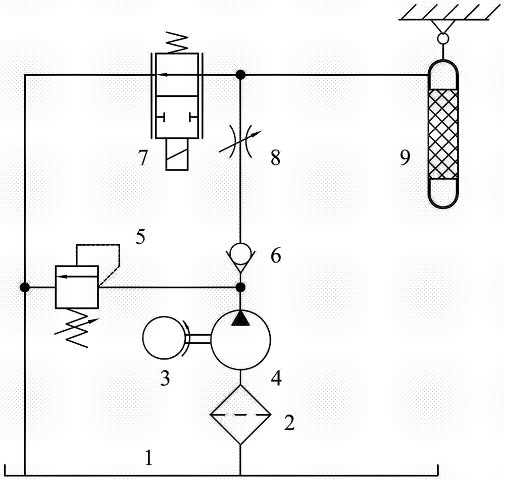
[0023] A water pressure artificial muscle hydraulic drive and control system, including a motor 3, a water hydraulic pump 4, a water tank 1, a filter 2, an overflow valve 5, a one-way valve 6, a normally open proportional throttle control valve 7, a throttle Valve 8 and water pressure artificial muscle driver 9; the motor 3 is connected to the water hydraulic pump 4, the inlet of the water hydraulic pump 4 is connected to the water tank 1 through the filter 2, and the outlet of the water hydraulic pump 4 is respectively connected to the overflow The inlet of the valve 5 and the one-way valve 6, the outlet of the one-way valve 6 is connected with the throttle valve 8, and the throttle valve 8 is connected with the normally open proportional throttle control valve 7 and the hydraulic artificial muscle driver respectively. 9 connection, the outlet of the overflow valve 5 and the normally open proportional throttle control valve 7 are respectively connected to the water tank 1; the...

Embodiment 2

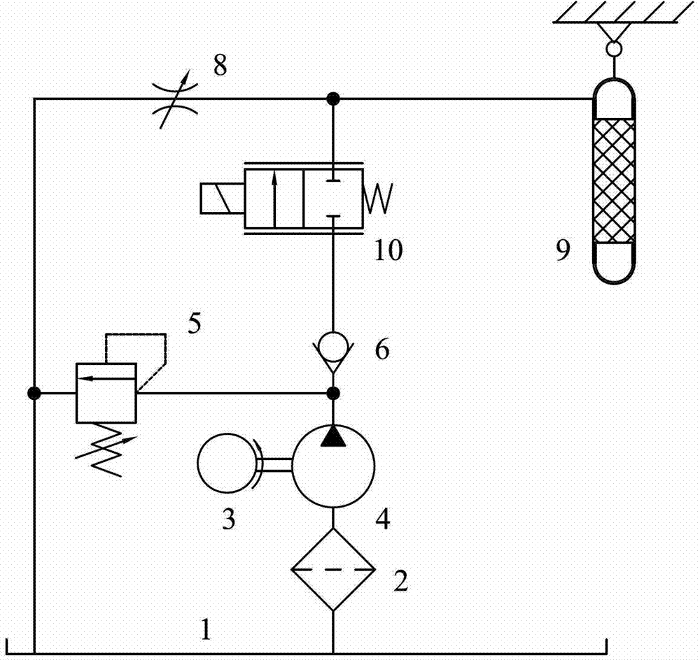
[0026] A water pressure artificial muscle hydraulic drive and control system, including a motor 3, a water hydraulic pump 4, a water tank 1, a filter 2, an overflow valve 5, a one-way valve 6, a normally closed proportional throttle control valve 10, a throttle Valve 8 and water pressure artificial muscle driver 9; the motor 3 is connected to the water hydraulic pump 4, the inlet of the water hydraulic pump 4 is connected to the water tank 1 through the filter 2, and the outlet of the water hydraulic pump 4 is respectively connected to the overflow The inlet of the valve 5 and the one-way valve 6, the outlet of the one-way valve 6 is connected with the normally closed proportional throttle control valve 10, and the normally closed proportional throttle control valve 10 is connected with the throttle valve 8 and the The water pressure artificial muscle driver 9 is connected, and the outlet of the overflow valve 5 and the throttle valve 8 are respectively connected to the water t...

Embodiment 3

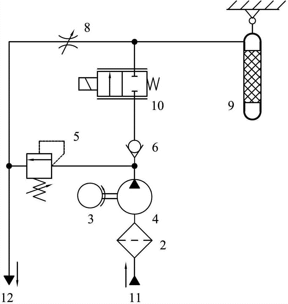
[0029] The water tank 1 of the present invention replaces the underwater environment.

[0030] When the present invention works, the filter 2 is connected to the water inlet 11, and the outlet of the overflow valve 5 and the throttle valve 8 are connected to the water outlet 12. The water hydraulic pump 4 obtains the water medium from the underwater environment through the filter 2 and the water inlet 11, and the water flowing through the overflow valve 5 and the throttle valve 8 is discharged into the underwater environment, the water tank 1 is omitted, and the pressure is realized. Automatic compensation also realizes the automatic pressure balance of the hydraulic artificial muscle driver 9 through the throttle valve 8 . Therefore, it is suitable for underwater or subsea operation machinery.

[0031]In conclusion, the hydraulic artificial muscle hydraulic drive and control system of the present invention has the advantages of simple structure, stable pressure regulation, w...


PUM


Abstract

The invention discloses a hydraulic artificial muscle hydraulic drive and control system, comprising a motor, a hydraulic pump, a water tank, a filter, an overflow valve, a one-way valve, a normally-open proportional throttle valve, a throttle valve and a hydraulic artificial muscle drive. The throttle valve is separately connected with the normally-open proportional throttle valve and the hydraulic artificial muscle drive, and the throttle valve together with the normally-open proportional throttle valve forms a B-shaped half bridge. Through the bridge formed by the normally-open proportional throttle valve and the adjusted throttle valve, pressure of the hydraulic artificial muscle drive being adjusted by the proportional throttle valve, the invention achieves control to the output force and placement of the hydraulic artificial muscle drive, suitable for control to a manipulator's joint driven by a hydraulic artificial muscle. The invention utilizes a hydraulic half bridge formed by a proportional throttle valve and an adjusted throttle valve to control the driving pressure of a hydraulic artificial muscle, and thereby, performance requirements to the hydraulic elements are reduced, and there's no need to install a proportional pressure-reducing valve. Furthermore, the system has the advantages of stable pressure adjustment, wide range and nice linearity.

Description

technical field [0001] The invention relates to a fluid-driven artificial muscle used in the fields of robots, special operation manipulators, and automated production lines, in particular to a hydraulic drive and control system for hydraulic artificial muscles. Background technique [0002] In the drive and control of robot joints, fluid-driven artificial muscles are a new type of drive, which can be divided into pneumatic artificial muscles and hydraulic artificial muscles. Pneumatic artificial muscles have been applied in the fields of robots and automated production lines, and have the advantages of simple structure, smooth movement, and large output force / weight ratio. The hydraulic artificial muscle not only has the advantages of simple structure, but also helps to achieve miniaturization and light weight. Compared with pneumatic artificial muscles, it has higher output force, faster response speed and lower working noise. Artificial muscles have no relative friction ...

Claims


Application Information

Patent Timeline
Patent Type & Authority Patents(China)
IPC IPC(8): F15B11/02
Inventor 张增猛弓永军
Owner DALIAN MARITIME UNIVERSITY
Learn More