
Pressure regulating mechanism with two freedom degrees

A technology of pressure regulating mechanism and degree of freedom, applied in the direction of mechanical equipment, fluid flow, etc., can solve the problems of limited pressure regulating range and narrow application range of pressure regulating mechanism, and achieve the effect of wide application range, stable pressure regulation and convenient use

Active Publication Date: 2013-06-19
ZHEJIANG UNIV OF TECH
View PDF3 Cites 2 Cited by
  • Summary
  • Abstract
  • Description
  • Claims
  • Application Information

AI Technical Summary

Problems solved by technology

The traditional pressure regulating mechanism has only one movement mode, which makes the application range of the pressure regulating mechanism narrow and the pressure regulating range is limited

Method used


Image

  • Pressure regulating mechanism with two freedom degrees
  • Pressure regulating mechanism with two freedom degrees
  • Pressure regulating mechanism with two freedom degrees

Examples


Embodiment 1

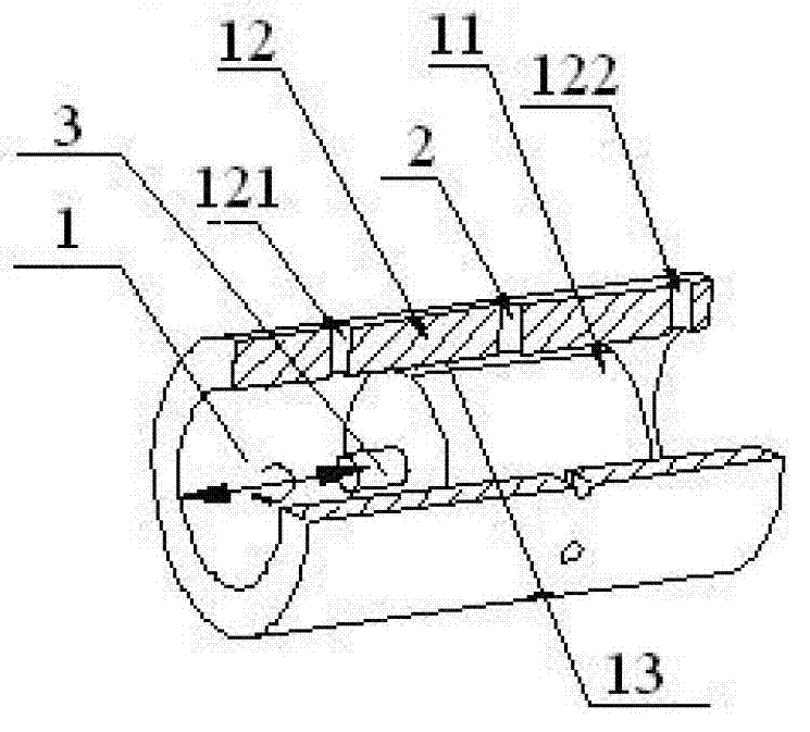
[0029] Embodiment 1 The two-degree-of-freedom pressure regulating mechanism described in the present invention includes a fluid laminar flow realization mechanism 1, several pressure-taking points 2 and a two-degree-of-freedom regulating mechanism 3;

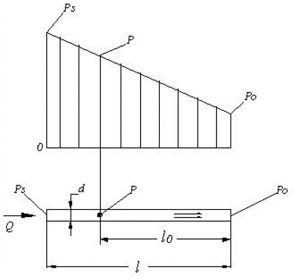
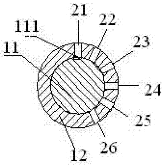
[0030] The fluid laminar flow realization mechanism 1 includes a valve core 11 and a valve sleeve 12; the side wall of the valve core 11 is axially provided with several through grooves 111 that run through the head and tail of the valve core, and the through grooves 111 and the valve sleeve 12 form a The gap 13 in the gap 13 communicates with the oil inlet 121 and the oil outlet 122. The gap 13 is a laminar laminar flow channel, and the fluid flow in the gap 13 presents a laminar flow state. The pressure distribution presents a stable linear distribution; when the number of the two pressure-taking points is one, the side wall of the valve core 11 is axially provided with a plurality of through grooves 111; when the number of the...


PUM


Abstract

A pressure regulating mechanism with two freedom degrees comprises a fluid laminar flow implementing mechanism, a plurality of pressure measuring points connecting with different pressure regulating mechanisms and a freedom degree regulating mechanism. The fluid laminar flow implementing mechanism comprises a valve core and a valve sleeve. A plurality of through grooves penetrating through the head and the tail of the valve core are axially formed in the side wall of the valve core, clearances formed by the through grooves and the valve sleeve are communicated with an oil inlet and an oil outlet, the flow of the fluid in the clearances is of a laminar flow state, and the pressure distribution of the oil inlet and the oil outlet is of stable linear distribution. The pressure measuring points are pressure measuring holes penetrating through the valve sleeve, and the pressure measuring holes are communicated with the clearances. The pressure measuring point position regulating mechanism comprises the valve core and a pushing component pushing the valve core to move inside the valve sleeve at two freedom degrees of a straight line mode and a rotating mode. The pressure regulating mechanism with the two freedom degrees has the advantages that the valve core has the motions of two freedom degrees of the straight line motion and the rotating motion simultaneously, the plurality of pressure measuring points can be connected with different pressure regulating mechanisms, the plurality of through grooves can regulate the range of the pressure regulating, and therefore the pressure regulating mechanism is enabled to be wide in application range, capable of being controlled in multiple points, stable in pressure regulating, and convenient to use.

Description

technical field [0001] The invention relates to a dual-degree-of-freedom pressure regulating mechanism. Background technique [0002] The fluid control element valve is generally composed of a valve core and a valve body, and the shoulder shaft of the valve core has relative sliding and rotating dual degrees of freedom in the valve body hole. General pressure control components such as relief valves, pressure reducing valves, sequence valves, etc., they all use the local pressure loss of the fluid in the small resistance hole to achieve pressure control, and they only use the valve core shoulder shaft in the valve body. One degree of freedom of movement within the hole—slide or turn—to control pressure. The traditional pressure regulating mechanism has only one movement mode, which makes the application range of the pressure regulating mechanism narrow and the pressure regulating range limited. Contents of the invention [0003] In order to solve the problem that the cur...

Claims


Application Information

Patent Timeline
IPC IPC(8): F15D1/02
Inventor 裴翔
Owner ZHEJIANG UNIV OF TECH
Learn More