Electric wave darkroom

A technology for anechoic chambers and absorbing materials, applied in the field of anechoic chambers, can solve the problems of manpower and time

Inactive Publication Date: 2013-06-19
WARECONN TECH SERVICE (TIANJIN) CO LTD
View PDF5 Cites 11 Cited by
  • Summary
  • Abstract
  • Description
  • Claims
  • Application Information

AI Technical Summary

Problems solved by technology

Therefore, when performing EMC tests in different frequency bands, it is necessary to transfer the electronic device under test between different anechoic chambers, which requires a lot of manpower and time.

Method used


Image

  • Electric wave darkroom
  • Electric wave darkroom
  • Electric wave darkroom

Examples


Embodiment Construction

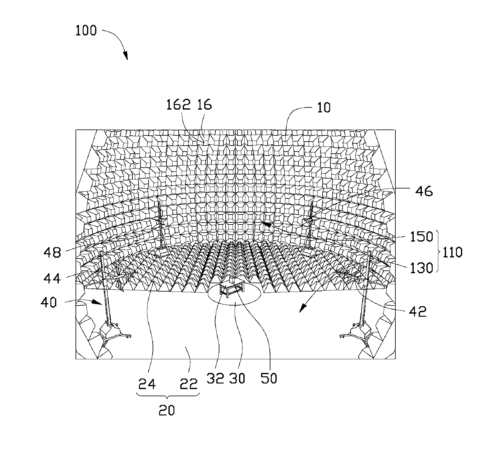
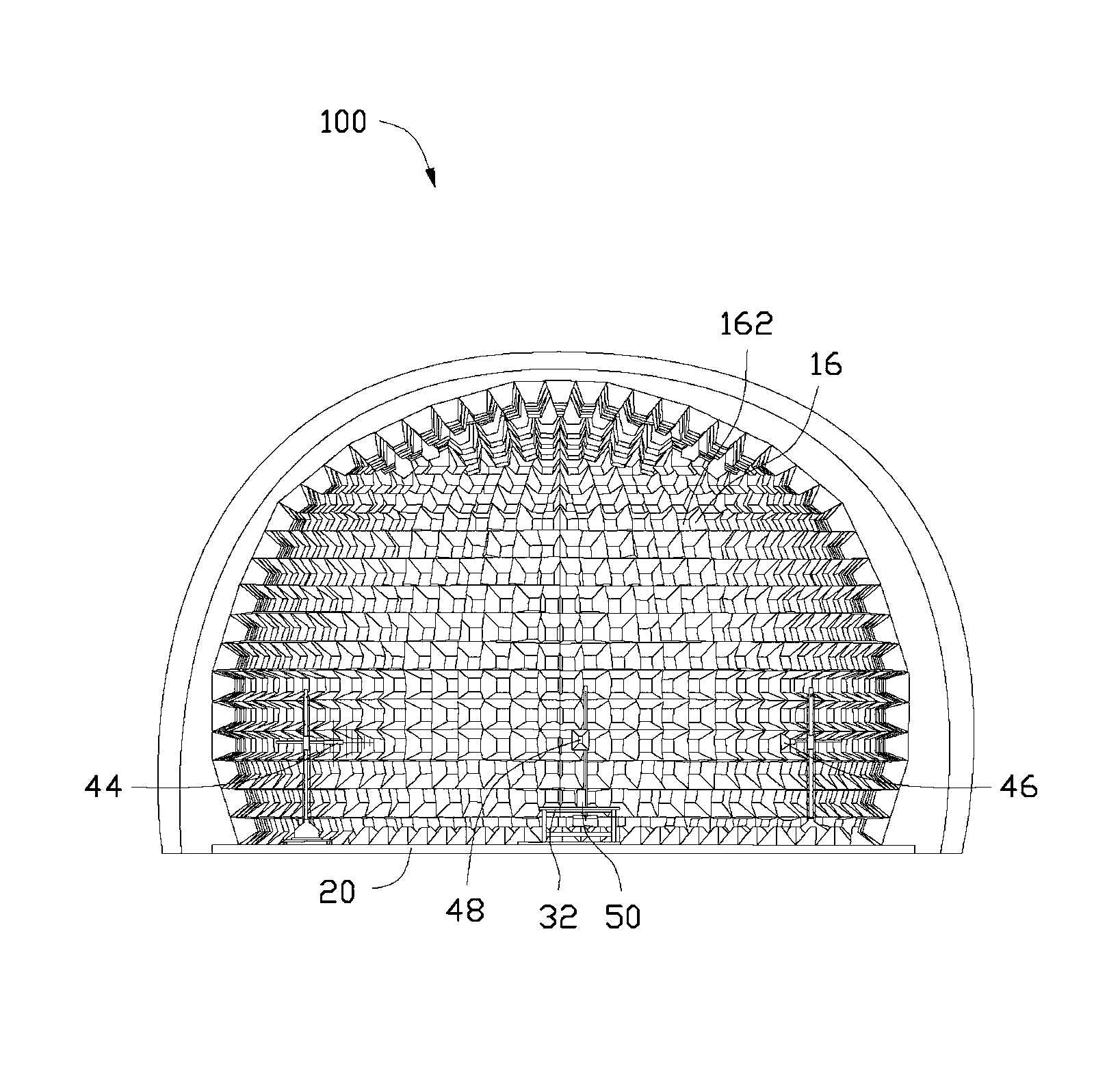
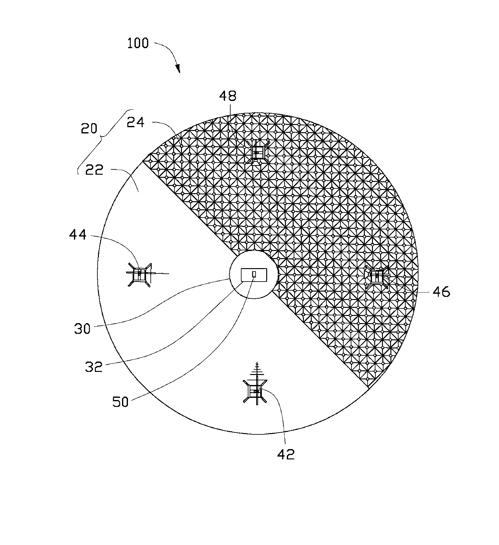
[0012] see figure 1 and figure 2 , the anechoic chamber 100 of the preferred embodiment of the present invention includes a peripheral wall 10 , a bottom surface 20 , a rotating platform 30 and an antenna array 40 . The peripheral wall 10 of the anechoic chamber 100 is in the shape of a hemisphere, and the bottom surface 20 is a circle. The peripheral wall 10 covers the bottom surface 20 and together with the bottom surface 20 encloses a substantially hemispherical closed accommodating space 110 . Both the rotating platform 30 and the antenna array 40 are located inside the accommodating space 110 and placed on the bottom surface 20 , and the rotating platform 30 and the antenna array 40 are placed at a certain distance. The anechoic chamber 100 can be used for electromagnetic compatibility testing of electromagnetic radiation sources such as computers or televisions.

[0013] The inner surface of the surrounding wall 10 is covered with a wave-absorbing material 16, and th...


PUM


Abstract

Disclosed is an electric wave darkroom. The electric wave darkroom comprises peripheral walls and a bottom surface, wherein wave-absorbing materials are laid on inner surfaces of the peripheral walls. The bottom surface is round and is divided into two semi-circle fields along one diameter, wherein one semi-circle bottom surface is a reflecting and grounding flat plate, and wave-absorbing materials are laid on the other semi-circle bottom surface.

Description

technical field [0001] The invention relates to the field of electromagnetic testing, in particular to an anechoic chamber. Background technique [0002] General electromagnetic compatibility (Electromagnetic Compatibility, EMC) tests need to use an anechoic chamber as a test site. Generally, an anechoic chamber is divided into a fully anechoic chamber and a semi-anechoic chamber. The inner surface of a full anechoic chamber is completely covered with absorbing materials, while a part of the inner surface of a semi-anechoic chamber is covered with absorbing materials. General information technology equipment (such as computers) needs to be tested in two frequency bands of low frequency (usually 30MHz~1GHz) and high frequency (usually 1GHz~6GHz) when conducting electromagnetic compatibility tests. Generally speaking, the low-frequency band test needs to be carried out in a semi-anechoic chamber, and the high-frequency band test needs to be carried out in a fully anechoic ch...

Claims


Application Information

Patent Timeline
Patent Type & Authority Applications(China)
IPC IPC(8): G01R1/18G01R31/00
CPCG01R29/0821G01R31/001
Inventor 何等乾
Owner WARECONN TECH SERVICE (TIANJIN) CO LTD
Why Eureka
Try Eureka