
Method of controlling distribution gradient of filled elements in soaking and filling of plasm

A technology of element distribution and immersion injection, applied in the direction of electrical components, circuits, discharge tubes, etc., can solve problems such as no better solution

Inactive Publication Date: 2013-06-19
INST OF MICROELECTRONICS CHINESE ACAD OF SCI
View PDF3 Cites 0 Cited by
  • Summary
  • Abstract
  • Description
  • Claims
  • Application Information

AI Technical Summary

Problems solved by technology

At present, there is no better solution to the above problems

Method used


Image

  • Method of controlling distribution gradient of filled elements in soaking and filling of plasm
  • Method of controlling distribution gradient of filled elements in soaking and filling of plasm
  • Method of controlling distribution gradient of filled elements in soaking and filling of plasm

Examples


Embodiment 1

[0024] This embodiment has the above-mentioned benefits of multi-energy injection, and its process method is also as described above, and its injection energy or injection negative bias voltage changes continuously with time, such as Figure 4 to Figure 7 shown. The implanted ion energy or negative bias voltage varies monotonically from the lowest energy or bias voltage to the highest energy or bias voltage or from the highest energy or bias voltage to the lowest energy or bias voltage over time. The implanted ion energy or negative bias voltage can also monotonically change from the lowest energy or bias voltage to the highest energy or bias voltage with time and then monotonically change to the lowest energy or bias voltage with time, such as Figure 6 shown; or from the highest energy or bias voltage over time to the lowest energy or bias voltage and then monotonically changing over time to the highest energy or bias voltage. The implanted ion energy or negative bias volta...

Embodiment 2

[0026] This embodiment has the above-mentioned benefits of multi-energy injection, and its process method is also as described above, and its injection energy or injection negative bias voltage varies discontinuously with time, such as Figure 8 . The implanted ion energy or negative bias voltage changes monotonously and discontinuously from the lowest energy or bias voltage to the highest energy or bias voltage over time, and the duration t1 of each energy or bias voltage can be equal or different, and two adjacent The energy or bias voltage intervals t2 are equal or unequal. Similar to Embodiment 1, each implanted ion energy or negative bias voltage can also monotonically and discontinuously change from the lowest energy or bias voltage to the highest energy or bias voltage over time and then change to the lowest energy or bias voltage; or from Highest energy or bias voltage over time to lowest energy or bias voltage and back to highest energy or bias voltage; or with some ...


PUM


Abstract

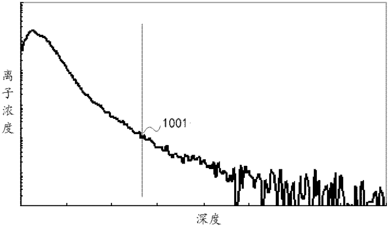
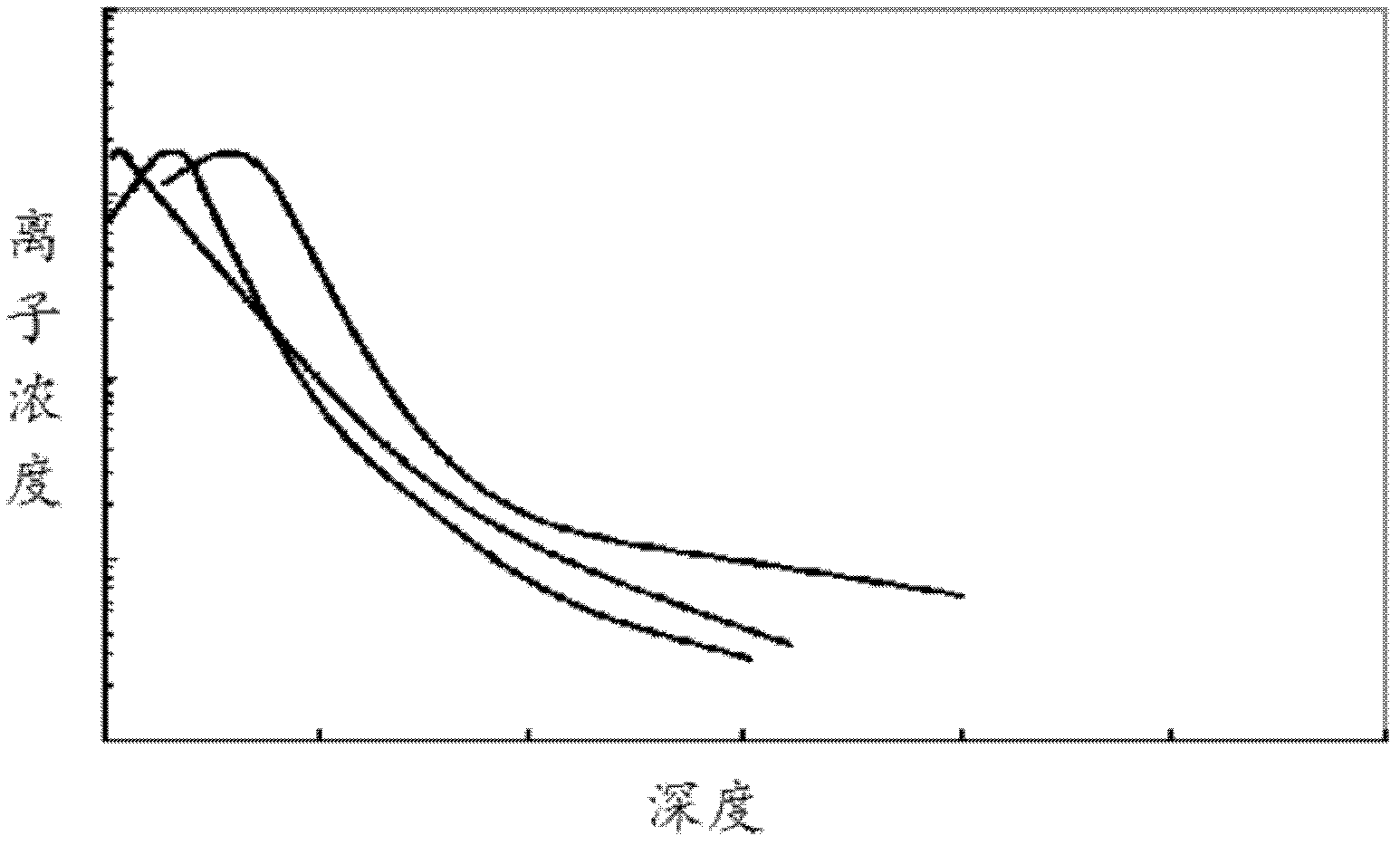
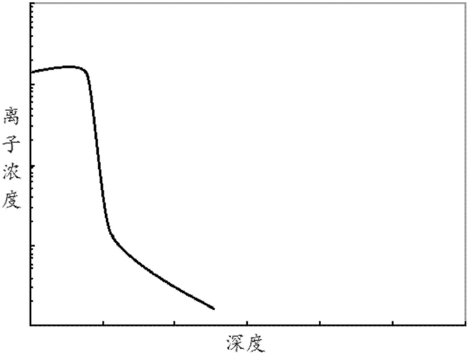
The invention discloses a method of controlling distribution gradient of filled elements in soaking and filling of plasm and belongs to the technical field of semi-conductor manufacture. According to the method of controlling the distribution gradient of the filled elements in soaking and filling of the plasm, filling and mixing of ions are performed in a manner of multiple kinds of energy filling. The multiple kinds of energy relate to multiple kinds of energy in an energy interval where the lowest energy the highest energy exists. The lowest energy is the minimum energy for achieving that mixed elements are filled but do not deposit on the surface of a silicon substrate. The highest energy is the maximum filling energy which can meet filling junction depth. With the method of controlling the distribution gradient of the filled elements in soaking and filling of the plasm, condensation of the mixed ions is distributed along the depth and in compliance with Gaussian distribution and condensation of the filled elements is abruptly distributed on a PN place.

Description

technical field [0001] The invention relates to the technical field of plasma immersion implantation, in particular to a method for controlling the distribution gradient of implanted elements in plasma immersion implantation. Background technique [0002] As the feature size of CMOS devices continues to shrink, the semiconductor process has entered the 32 / 22nm technology node, and the source-drain junction depth has entered within 10nm. In order to meet the requirements of ultra-shallow junctions, the energy of dopant ions enters the sub-kilovolt range. The traditional beamline ion implantation technology has been unable to meet the requirements of ultra-shallow junction fabrication in technology nodes below 32nm. Plasma immersion implantation is considered to be a new technology to replace beamline ion implantation technology to produce ultra-shallow junctions. However, plasma immersion implantation also has challenges in the manufacture of ultra-shallow junctions. The di...

Claims


Application Information

Patent Timeline
Patent Type & Authority Applications(China)
IPC IPC(8): H01J37/317
Inventor 汪明刚李超波夏洋
Owner INST OF MICROELECTRONICS CHINESE ACAD OF SCI
Learn More