Decompression unit

A technology of decompression port and pressure difference, applied in the direction of aircraft floor, aircraft parts, aircraft accessories, etc., can solve the problems of inability to clearly define elasticity, expensive, unable to guarantee rapid trigger time, etc., to achieve high resistance, simple transportation, Create easy effects

Active Publication Date: 2013-06-19
FACC
View PDF8 Cites 0 Cited by
  • Summary
  • Abstract
  • Description
  • Claims
  • Application Information

AI Technical Summary

Problems solved by technology

The disadvantage here is that the elasticity to be overcome cannot be clearly defined
This st

Method used


Image

  • Decompression unit
  • Decompression unit
  • Decompression unit

Examples


Embodiment Construction

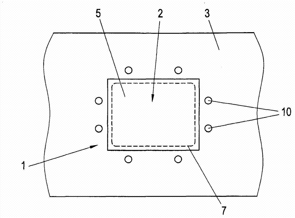
[0026] figure 1 Shown is a view of a decompression unit 1 in a decompression opening 2 of a wall element 3 in an aircraft. Correspondingly, the pressure relief opening 2 in the wall element 3 is covered by a panel 5 formed by at least one hardened prepreg layer 6 having at least one boundary seam 7 filled with hardened resin as Rated breaking point (refer to Figure 4a and 4b ). The parting seam 7 in the panel 5 ensures that the fibers of the prepreg layer, in particular the glass fibers, are broken and thus form a desired breaking point which is only filled with the cured resin. When a predetermined differential pressure Δp is exceeded, the brittle resin in the parting seam 7 breaks and the panel 5 moves out of the pressure relief opening 2 , so that a pressure compensation between the two sides of the wall element 3 can take place.

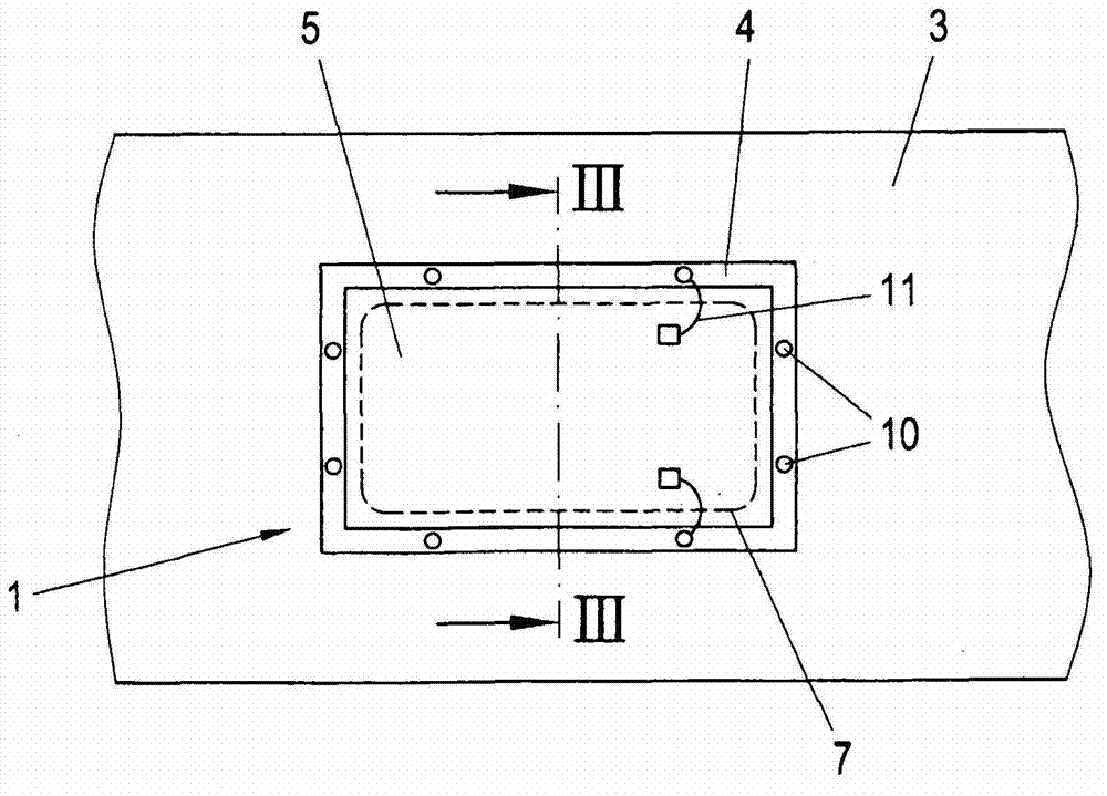
[0027] figure 2 shown based on figure 1 Rear view of the decompression unit 1. Here, the panel 5 is connected to the wall element 3 via...


PUM

PropertyMeasurementUnit
Widthaaaaaaaaaa

Abstract

The invention relates to a decompression unit (1) for use in a decompression opening (2) of a wall element (3) of an aircraft, having a panel (5) which can be mounted via a frame (4) in or over the decompression opening (2) which panel (5) can be moved out of the frame (4) at a predetermined differential pressure (delta p) in order to open the decompression opening (2). In order to form a decompression unit (1) of as simple a design as possible and with an optimum response behaviour, provision is made for the panel (5) to be formed by at least one hardened prepreg layer (6) with at least one separating joint (7) which is filled with cured resin as a weak point, which separating joint (7) breaks when the predetermined differential pressure (delta p) is exceeded.

Description

technical field [0001] The invention relates to a decompression unit for use in a decompression opening of a wall element of an aircraft, comprising a panel that can be fixed in or on the decompression opening by means of a frame, the panel being at a predetermined pressure difference Can be moved out of the frame to open the relief opening. Background technique [0002] During aircraft flight, the pressure in the cabin is increased in order to provide passengers and crew with normal ambient conditions even at normal flight altitudes. Accordingly, the internal pressure of the aircraft is increased relative to the environment, so that the cabin is constructed in the form of a pressurized cabin. Corresponding outlet valves are provided for regulating the pressure in the aircraft cabin. [0003] Most aircraft have a plurality of sections which are divided by corresponding wall elements. For example, the passenger cabin and the cargo compartment of a passenger aircraft are se...

Claims


Application Information

Patent Timeline
IPC IPC(8): B64C1/10B64C1/20
CPCB64C1/10B64C2001/009B64C1/00
Inventor E·帕明格B·克梅雷尔
Owner FACC
Why Eureka
Try Eureka