Pipette tips

A pipette tip, liquid technology, applied in measuring tubes/pipettes, laboratory utensils, laboratory containers, etc., can solve problems such as high energy consumption

Active Publication Date: 2013-06-26
EPPENDIRF AG
View PDF6 Cites 13 Cited by
  • Summary
  • Abstract
  • Description
  • Claims
  • Application Information

AI Technical Summary

Problems solved by technology

As long as the mating and ejection are done by motor drives, these

Method used


Image

  • Pipette tips
  • Pipette tips
  • Pipette tips

Examples


Embodiment Construction

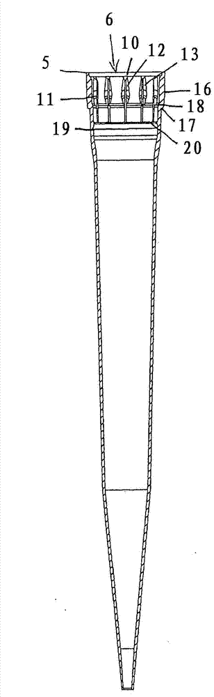
[0039] In this application, the designations "upper" and "lower" refer to the orientation of the pipette tip in the pipette, where the pipette tip is oriented vertically, with the lower opening on the bottom side and the upper opening on the top side .

[0040] In the following description of the different embodiments, the same features are denoted by the same reference numerals.

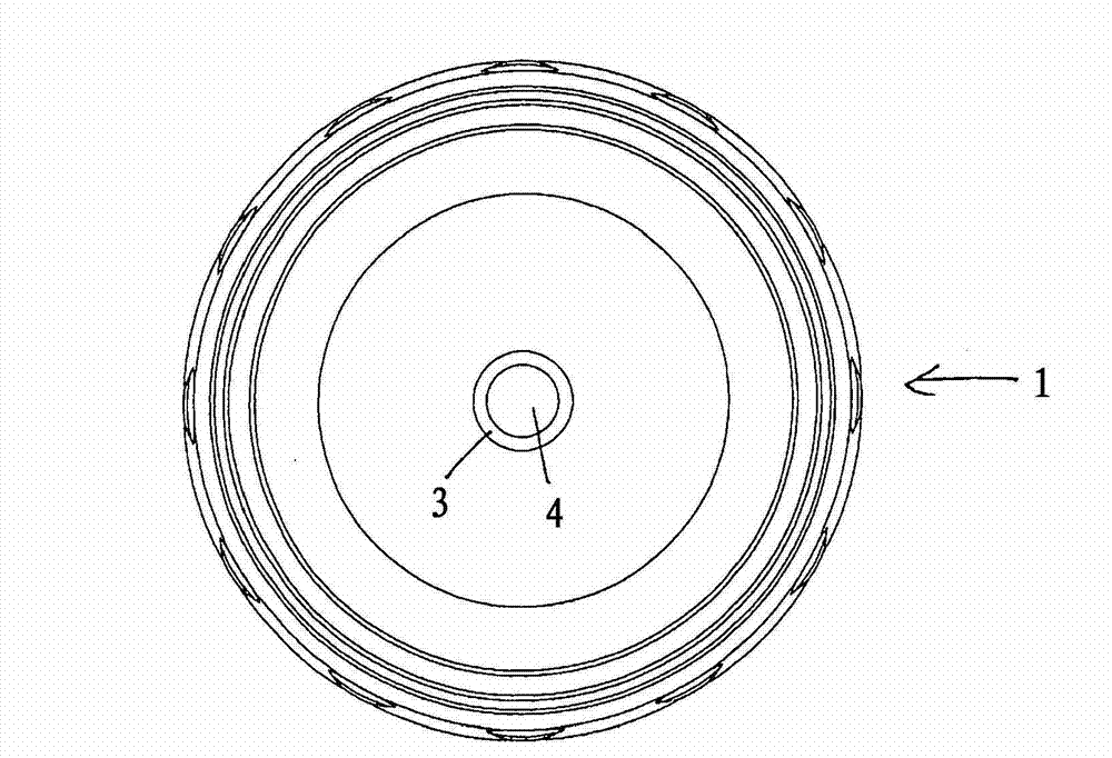
[0041] According to FIG. 1 , a pipette tip 1 has an elongated tubular body 2 with a lower opening 4 at a lower end 3 and a plug opening 6 at an upper end 5 . The lower opening 4 is smaller than the upper opening 6 .

[0042] The inner and / or outer diameter of the tubular body 2 generally increases from the lower end 4 towards the upper end 6 . In the example, the tubular body 2 has a conical front part 7 on the bottom side, a conical smaller central part 8 above it and a head part 9 above the central part 8 . The pipette tip 1 according to the invention can also expand in another way, in particul...


PUM


Abstract

The tip (1) has a seat section provided next to an upper opening (6) at an inner periphery. The seat section includes a holding region with radial inward projecting part, axially extending ribs and a sealing region that is formed below the holding region. The sealing region is formed, so that the tip is held and sealed on a neck, during insertion of the tip with the seat section on the neck by fitting force. The ribs are plastically deformed, and an elastic deformation occurs on an outer side of the ribs in the seat section.

Description

technical field [0001] The present invention relates to a pipette tip. Background technique [0002] Along with pipettes and other metering devices, pipette tips are used to meter liquids. In the following, pipettes and metering devices are collectively referred to as "pipette devices". The pipette tip has an elongated tubular body with a pipetting opening at the lower end and a plug opening for plugging into an accessory of a pipetting device. Standardized conical attachments with standard geometry are known, are used consistently by many manufacturers and are characterized for each pipette tip by the average diameter ratio and cone angle ratio of the conical attachments. [0003] The suction device comprises a gas discharge element, usually a cylindrical piston having an axially movable therein. The gas exhaust element is connected to the passage hole of the accessory. By pressing the attachment of the pipette into the upper opening of the pipette tip, the pipette tip ...

Claims


Application Information

Patent Timeline
IPC IPC(8): B01L3/02
CPCB01L3/0275B01L2200/025B01L2200/026B01L2200/087
Inventor J·贝泽
Owner EPPENDIRF AG
Why Eureka
Try Eureka