Laser welding device and welding method

A technology of laser welding and welding method, applied in laser welding equipment, welding equipment, metal processing equipment, etc., can solve the problems of increased laser welding difficulty, unstable welding process, and difficulty in penetrating thick plates, so as to improve welding stability , reduce the shielding effect, avoid the effect of focus drift

Active Publication Date: 2013-06-26
HANS LASER TECH IND GRP CO LTD
View PDF6 Cites 29 Cited by
  • Summary
  • Abstract
  • Description
  • Claims
  • Application Information

AI Technical Summary

Problems solved by technology

However, as the thickness of the plate increases, the difficulty of laser welding increases significantly
The original thin plate welding method is difficult to penetrate thick plates (thickness above 14mm), so it is difficult to weld thick plates, thick plate penetration welding has become a major problem in the field of laser welding
In order to penetrate the thick plate, a higher power laser must be used to weld the thick plate, and the high power laser is easy to form humps, splashes and focus drift caused by optical components on the surface of the workpiece to be welded, so that the thick plate Welding process is unstable for soldering

Method used


Image

  • Laser welding device and welding method
  • Laser welding device and welding method
  • Laser welding device and welding method

Examples


Embodiment Construction

[0030] In order to facilitate the understanding of the present invention, the present invention will be described more fully below with reference to the associated drawings. Preferred embodiments of the invention are shown in the accompanying drawings. However, the present invention can be embodied in many different forms and is not limited to the embodiments described herein. Rather, these embodiments are provided for the purpose of making the disclosure of the present invention more thorough and comprehensive.

[0031] It should be noted that when an element is referred to as being “fixed” to another element, it can be directly on the other element or there can also be an intervening element. When an element is referred to as being "connected to" another element, it can be directly connected to the other element or intervening elements may also be present.

[0032] Unless otherwise defined, all technical and scientific terms used herein have the same meaning as commonly un...


PUM


Abstract

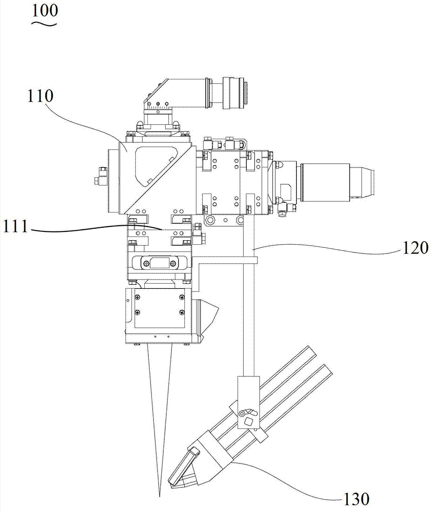
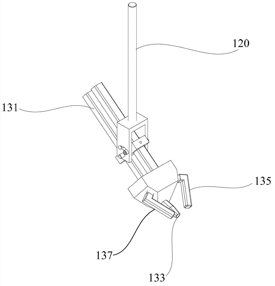
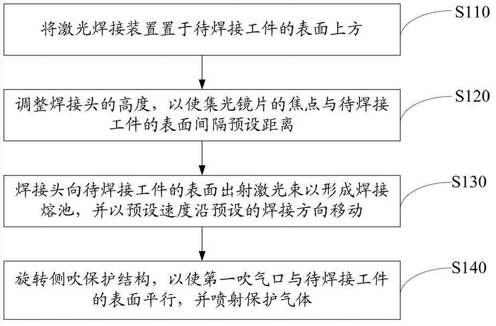
The invention discloses a laser welding device. According to the invention, the aggregating lens of a welding head is a long-focus lens, so that the welding head can be placed at a position far away from a welding pool during welding, the influence of thermal radiation of the welding pool on optical devices in the welding head can be reduced and the focus drifting of the aggregating lens is avoided; in addition, a first air blowing port of a side-blow protecting structure is capable of spraying protective gas into the welding pool during the welding and plasma above the welding pool can be blown away, so that the height of plasma flame can be reduced, the shielding effect of the plasma on laser beams is reduced and humps are avoided; and in conclusion, the laser welding device is capable of effectively improving the welding stability in a thick plate welding process. In addition, the invention also provides a welding method.

Description

technical field [0001] The invention relates to a laser welding process, in particular to a laser welding device and a welding method. Background technique [0002] Laser welding technology has the advantages of wide application range, high efficiency and low loss, and has been widely used in welding plates. Laser welding has a better welding effect for plates with a small thickness (thickness less than 10 mm). However, as the thickness of the plate increases, the difficulty of laser welding increases significantly. The original thin plate welding method is difficult to penetrate thick plates (thickness above 14 mm), so it is difficult to weld thick plates, thick plate penetration welding has become a major problem in the field of laser welding. In order to penetrate the thick plate, a higher power laser must be used to weld the thick plate, and the high power laser is easy to form humps, splashes and focus drift caused by optical components on the surface of the workpiece...

Claims


Application Information

Patent Timeline
Patent Type & Authority Applications(China)
IPC IPC(8): B23K26/20B23K26/14B23K26/21
Inventor 邓时累张明军唐景龙陈根余陈燚高云峰
Owner HANS LASER TECH IND GRP CO LTD
Why Eureka
Try Eureka