Accessory clamping mechanism and power tool with same

A technology of clamping mechanism and power tool, which is applied in the direction of manufacturing tools and portable motorized devices, and can solve the problems of reducing the versatility of the accessory clamping mechanism.

Active Publication Date: 2013-06-26
NANJING CHERVON IND
View PDF8 Cites 6 Cited by
  • Summary
  • Abstract
  • Description
  • Claims
  • Application Information

AI Technical Summary

Problems solved by technology

[0005] However, when using this accessory clamping mechanism to clamp accessories, the shank of the accessory must pass through the working mandrel, so the shank of the accessory is provided with an opening, so ...

Method used


Image

  • Accessory clamping mechanism and power tool with same
  • Accessory clamping mechanism and power tool with same
  • Accessory clamping mechanism and power tool with same

Examples


Embodiment Construction

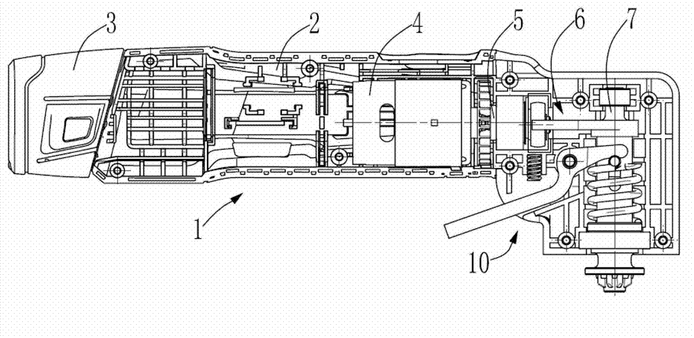
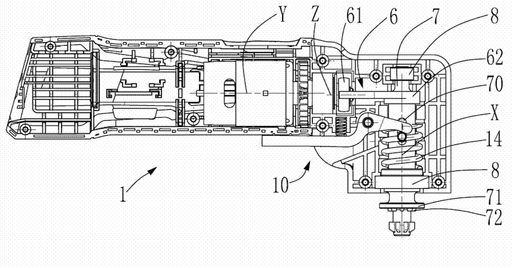
[0032] Such as Figure 1-2As shown, a power tool 1 with an accessory clamping mechanism is disclosed in the first embodiment of the present invention. In this embodiment, an oscillating power tool is taken as an example for illustration. Those skilled in the art can understand that the accessory The clamping mechanism can also be used for other power tools such as angle grinders, sanders, and circular saws. The power tool 1 includes a housing 2 , a power source 3 connected to the housing 2 , a motor 4 and a drive shaft 5 accommodated in the housing 2 , a transmission mechanism 6 , a working spindle 7 and an accessory clamping mechanism 10 .

[0033] The power source 3 provides power to the motor 4. It can be understood that the power source 3 can be a power source known to those skilled in the art such as a battery pack, an AC power supply, an air compressor or a mobile power supply. The drive shaft 5 is driven by the motor 4 and is rotatable about its axis of rotation Y (sec...


PUM


Abstract

The invention provides an accessory clamping mechanism which is used for clamping an accessory on a working arbor flange of a power tool, and a working arbor is provided with a first longitudinal axis. The accessory clamping mechanism comprises at least one clamping piece, a push component, an elastic piece, a driving component and a motion conversion piece. The push component supports the clamping piece, and the push component and the clamping piece are driven by a driving piece to move along the first longitudinal axis. The push component is pressed towards a clamping position through the elastic piece. The driving component is used for enabling the push component and the clamping piece to move along the first longitudinal axis, the driving component comprises the driving piece, and the driving piece moves between a first position and a second position. On the first position, an accessory is arranged on the clamping position. On the second position, the accessory is arranged on a releasing position. The motion conversion piece drives the clamping piece to move along a direction different from the first longitudinal axis. The invention further provides a power tool with the accessory clamping mechanism.

Description

technical field [0001] The present invention relates to a clamping mechanism, in particular to a clamping mechanism for releasably securing an accessory to a work spindle; the invention also relates to a power tool with such a clamping mechanism, in particular to a A power tool with a clamping mechanism for releasably securing an accessory to a work spindle. Background technique [0002] At present, there are various power tools with accessory clamping mechanism on the market, one of which has a power tool with accessory clamping mechanism, including: a working spindle that drives the accessory, and the accessory is fixed on the end of the working spindle facing the tool between the holding part at the part and the fastening element; a mechanism for moving the fastening element between a release position in which the fastening element is removed from the working mandrel and a clamping position in which the fastening element bears against the holding part by means of a spring...

Claims


Application Information

Patent Timeline
IPC IPC(8): B25F5/00B25F3/00
Inventor 徐国生塞韦里茨·格奥尔基周红陶
Owner NANJING CHERVON IND
Why Eureka
Try Eureka