Supercharge Your Innovation With Domain-Expert AI Agents!

tool changing system

A tool replacement and tool technology, applied in the direction of manufacturing tools, manipulators, chucks, etc., can solve the problems such as the relative position of the locking bolts, operation failures, etc., to achieve high operational safety and availability, simple structure, and control costs.

Active Publication Date: 2016-01-13
KUKA SYSTEMS
View PDF11 Cites 0 Cited by
  • Summary
  • Abstract
  • Description
  • Claims
  • Application Information

AI Technical Summary

Problems solved by technology

In addition, the relative position of the locking bolts when the receiving parts collide is not specified, which may lead to malfunctions in operation

Method used


Image

  • tool changing system
  • tool changing system
  • tool changing system

Examples


Embodiment Construction

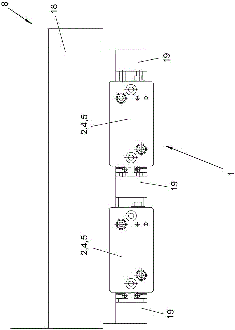
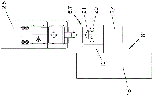
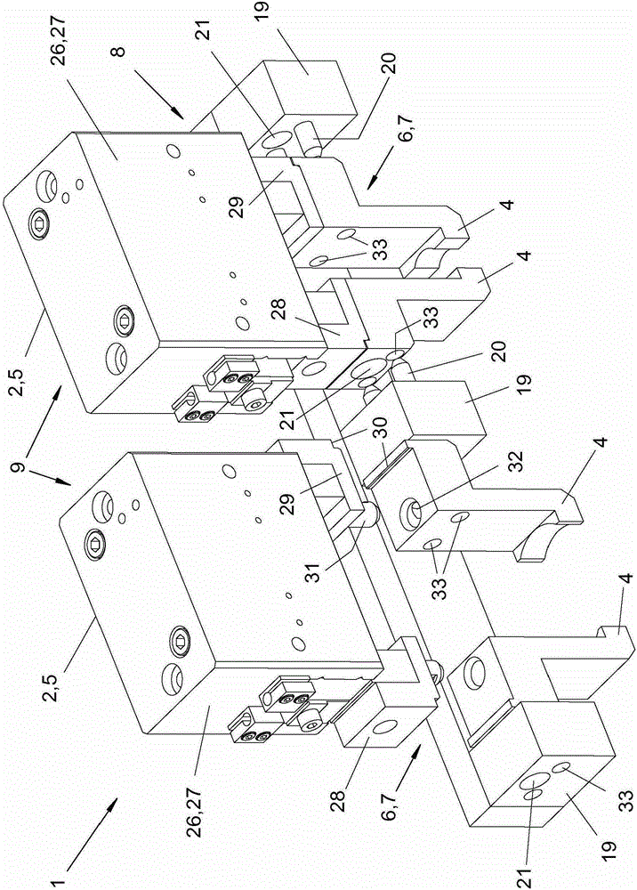
[0063] The invention relates to a tool changing system 1 and a method for changing tool parts 4 . The invention also relates to a machining device 3 equipped with a tool changing system 1 .

[0064] Figure 1 to Figure 4 A tool changing system 1 is shown with, for example, two multi-part tools 2 , which are designed, for example, as tongs, in particular parallel tongs. Each tool 2 consists of a tool part 5 , to which one or more exchangeable tool parts 4 are coupled by means of a coupling device 6 and an associated form-fitting locking device 7 .

[0065] Two tools 2 of the same type are shown in the figure to illustrate different operating positions. Alternatively, the number of tools 2 in the tool changing system 1 can be more or less than two. The tools 2 can be of the same type and have, for example, identical or similar tool parts 5 , which can be coupled with possibly all exchangeable tool parts 4 . Alternatively, the multi-part tools 2 can also be completely differe...


PUM


Abstract

The system (1) has a multipart tool (2) i.e. grippers, and a provision unit (8) i.e. magazine, for exchangeable tool parts (4, 5) i.e. gripping fingers. A coupling unit (6) is provided with a positive self-closing latching device (7) for operating the tool parts. A holder (19) is arranged with a force element (21) i.e. magnet such as permanent magnet, for exchanging the tool parts by the provision unit. The force element openingly acts on the latching device at the held tool parts. The holder and the exchangeable tool parts comprise positive guide elements. The guide elements are designed as parallel guide pin (20) and guide holes (33). An independent claim is also included for a working fixture.

Description

technical field [0001] The invention relates to a tool changing system for a multi-part tool. Background technique [0002] Patent document DD226826A1 discloses such a tool changing system. The tool is designed as a robotic gripper with replaceable jaws that can be received by the holder of the supply device. The tool has a base part connected to the robot hand, which has two receptacles (Aufnahme) mounted on it for travel, where each receptacle can be coupled with a gripper jaw and A locking bolt ensures this coupled state. To release the locking device, the receiving parts collide, whereby the locking screws are pressed against each other and into the open position, which enables coupling and decoupling of the clamping jaws. Locking devices of this type require corresponding shaping of the jaws. The locking device is arranged on the receptacle so that it is permanently loaded. Furthermore, the relative position of the locking bolts when the receptacles collide is not ...

Claims


Application Information

Patent Timeline
Patent Type & Authority Patents(China)
IPC IPC(8): B25J15/04
CPCB25J15/0475
Inventor 莱茵霍尔德·奈德
Owner KUKA SYSTEMS
Features
  • R&D
  • Intellectual Property
  • Life Sciences
  • Materials
  • Tech Scout
  • Unparalleled Data Quality
  • Higher Quality Content
  • 60% Fewer Hallucinations
Learn More