Roving frame

A technology of roving frame and roving, which is applied in textiles and paper making, etc., can solve the problem of inability to clean the roving frame reliably, and achieve the effect of reducing power, reliable cleaning and saving energy.

Inactive Publication Date: 2016-06-08
SAURER GERMANY GMBH & CO KG
View PDF10 Cites 1 Cited by
  • Summary
  • Abstract
  • Description
  • Claims
  • Application Information

AI Technical Summary

Problems solved by technology

None of the known arrangements of movable suction or blowing devices can reliably clean the entire surface below the drafting device in the roving frame

Method used


Image

  • Roving frame
  • Roving frame
  • Roving frame

Examples


Embodiment Construction

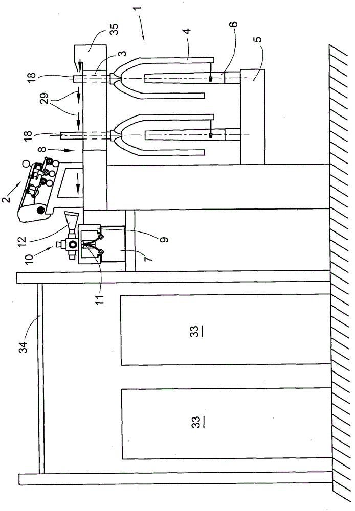
[0026] figure 1 A roving frame 1 according to the invention, also called a flyer roving frame, is shown with a drafting device 2 , a top beam 3 , a flyer 4 as well as a spindle rail 5 and a spindle bar 6 . figure 1 A side view of the roving frame is shown, which in turn shows its transverse view. Below the drafting device 2 there is a substantially flat outer surface 8 . This surface 8 extends from the region of the drafting device 2 to the flyer sleeve 18 .

[0027] The rovings are stored in cans 33 . The roving is fed to the drafting device 2 via guide rollers (not shown) fixed on the support tube 34 . The roving passes through the drafting device 2 and through the flyer sleeve 18 to the flyer 4 and finally is wound on a roving or flyer bobbin (not shown) arranged on the spindle bar 6 . Along the longitudinal direction of the roving frame 1 a large number of other stations are provided.

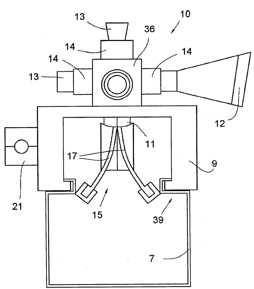
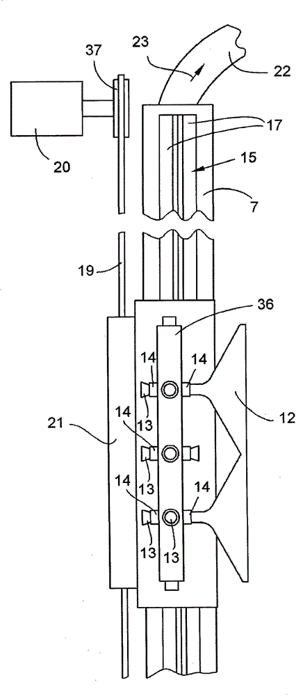
[0028] Near the surface 8 to be cleaned below the drafting device 2, an air blowin...


PUM


Abstract

The machine (1) has carriage (9) that is moved along the suction channel (7) on a guide track. The carriage is provided with air guide element (10) having an air delivery element (11) and a suction opening (12). The suction channel and the air transfer element are formed so that the air guide element is acted upon by negative pressure and suction is produced at the suction opening. The suction opening is provided facing towards the surface (8) and arranged between the drafting unit (2) and the surface.

Description

technical field [0001] The invention relates to a roving frame for producing rovings wound on roving bobbins. The roving frame has a drafting device and an upper rail with a flyer rotatable about a corresponding central axis and a flyer sleeve for the passage of the roving. Furthermore, the roving frame also includes a spindle rail with a spindle bar receiving the roving bobbins. The surface lying below the drafting device extends in the transverse direction of the roving frame at least from the area of ​​the drafting device to the flyer sleeve. The vacuumed suction channel is arranged on the end of the surface below the drafting device facing the drafting device and extends in the longitudinal direction of the roving frame. Background technique [0002] The roving frame (also called flyer roving frame) processes the cooked sliver into rovings which are wound onto roving bobbins. Roving bobbins are also called flyer bobbins. The flyer bobbins can be further processed int...

Claims


Application Information

Patent Timeline
Patent Type & Authority Patents(China)
IPC IPC(8): D01H11/00
CPCD01H11/006
Inventor S·艾泽勒卡尔-海因茨·麦克
Owner SAURER GERMANY GMBH & CO KG
Why Eureka
Try Eureka