Steady transition diversion system for rapid and slow flow in river confluence area

A technology of intersection and rapids, applied in the field of river dynamics, it can solve problems such as land use tension and difficulty in node design, and achieve the effects of reducing requisition, eliminating water flow separation and eddy, and increasing water passing area.

Active Publication Date: 2015-08-05
HOHAI UNIV
View PDF4 Cites 0 Cited by
  • Summary
  • Abstract
  • Description
  • Claims
  • Application Information

AI Technical Summary

Problems solved by technology

[0003] The present invention proposes a rapid and slow flow smooth transition diversion system in the confluence area of ​​rivers, the purpose of which is to overcome the problems of serious urban canalization, difficult node design, and tight land use. When the torrent enters the slow-flow channel, large-scale standing waves are generated to reduce the separation of eddies and water flow. On the basis of ensuring the designed flood flow, the water level of the confluence is minimized to reduce the occurrence of urban floods

Method used


Image

  • Steady transition diversion system for rapid and slow flow in river confluence area
  • Steady transition diversion system for rapid and slow flow in river confluence area
  • Steady transition diversion system for rapid and slow flow in river confluence area

Examples


Embodiment 1

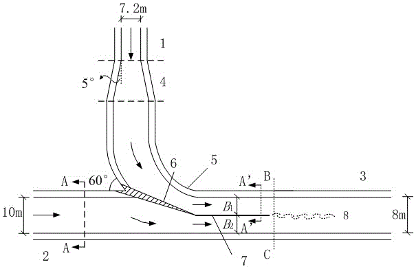
[0016] As shown in the attached figure, the structure of the rapid and slow flow smooth transition diversion system in the confluence area of ​​the river course includes the hydraulic jump energy dissipation section 4, the streamlined channel wall 5 and the jet flow control structure; the hydraulic jump energy dissipation section 4 is set before the intersection of the two channels On the rapid flow channel 1, the streamlined channel wall 5 is set between the hydraulic jump energy dissipation section 4 on the rapid flow channel 1 and the slow flow channel 2; the jet control structure is composed of a fish mouth 6 and a diversion wall 7, wherein the diversion wall 7 is set At the top of the fish mouth 6 and parallel to the slow flow channel 2; the fish mouth 6 is set at the intersection of the streamlined channel wall 5 and the slow flow channel 2, and extends to the center of the slow flow channel 2 to the smooth diversion channel 3.

[0017] The main function of the diversion ...


PUM


Abstract

The invention provides a rapid-slow flow smooth transition flow diversion system for a riverway intersection area. The structure of the rapid-slow flow smooth transition flow diversion system for the riverway intersection area is as follows: a hydraulic jump energy dissipation section is arranged on a rapid flow channel in front of intersection of two channels, and a streamline channel wall is arranged between the hydraulic jump energy dissipation section on the rapid flow channel and a slow flow channel; a jet flow control structure is composed of a fish mouth and a flow diversion wall, wherein the flow diversion wall is arranged at the top end of the fish mouth and is parallel with the slow flow channel; the fish mouth is arranged at an intersection point of the connection of the streamline channel wall and the slow flow channel and extends toward a slow flow channel center and extends to a stable flow diversion channel. The rapid-slow flow smooth transition flow diversion system for the riverway intersection area has the advantages that the phenomenon that large standing waves are formed when rapid flow directly enters the slow flow channel can be avoided, and channel flood discharge is benefited; the direction of the flow of the rapid flow channel can be changed stably, and the form of a flow line is changed smoothly; flow separation and vortexes are weakened and even eliminated, and the actual flow discharge area is increased; the jet flow control structure effectively lowers the water level of an affluxion mouth; the channel design flood discharge flow quantity is guaranteed, and the water level of the affluxion mouth is effectively controlled; and the rapid-slow flow smooth transition flow diversion system for the riverway intersection area is beneficial to popularization in a large area in areas with limited land and in city flood-prevention projects, and the expropriation of the land is greatly reduced.

Description

technical field [0001] The invention belongs to the technical field of river dynamics, and in particular relates to a diversion system for smooth transition of rapid and slow flows in river confluence areas. Background technique [0002] The needs of urban economic development and the limitation of urban land make river channelization serious and tend to concentrate. Once a flood occurs in a city, the consequences will be unimaginable, so very high requirements are put forward for the flood discharge design of the channel. The design of the channel itself is relatively simple, mainly based on the design of channel section size and bottom slope according to the amount of flood discharge; however, the design of channel-to-channel node connections is relatively complex and much more important. If the node design is not good, it is easy to cause the difficulty of flood discharge and cause urban flood disasters. The node connection between channels should be designed in accorda...

Claims


Application Information

Patent Timeline
Patent Type & Authority Patents(China)
IPC IPC(8): E02B3/02E02B5/02
Inventor 唐洪武袁赛瑜李行伟肖洋刘震
Owner HOHAI UNIV
Why Eureka
Try Eureka