
Display equipment and information processing method thereof

An information processing method and a display device technology, which are applied in the field of display devices and their information processing, can solve problems such as insufficient intelligence, lack of humanity, cumbersome two-handed operations, etc., and achieve easy and simple operation, improved convenience, and enhanced user experience. Effect

Active Publication Date: 2013-06-26
NUBIA TECHNOLOGY CO LTD
View PDF4 Cites 13 Cited by
  • Summary
  • Abstract
  • Description
  • Claims
  • Application Information

AI Technical Summary

Problems solved by technology

[0006] In view of this, the technical problem to be solved by the present invention is to provide a display device and its information processing method, so as to solve the problem that the existing display device is cumbersome to operate with both hands, or it is not enough to operate only after following the operation area displayed on the display screen. Intelligent, not humane and other issues

Method used


Image

  • Display equipment and information processing method thereof
  • Display equipment and information processing method thereof
  • Display equipment and information processing method thereof

Examples


Embodiment 1

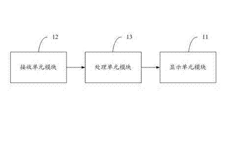
[0055] see figure 1 , which is a schematic diagram of a first embodiment of a display device according to the present invention.

[0056] A display device, which includes: a display unit module 11 , a receiving unit module 12 , and a processing unit module 13 .

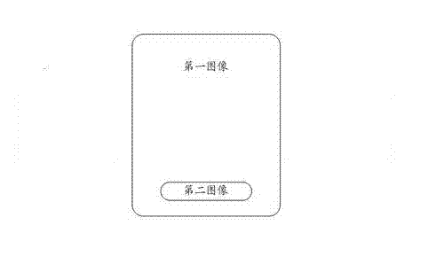
[0057] The display unit module 11 is used to display an image; wherein, the image includes a first image and a second image, such as figure 2 shown.

[0058] On the display screen of the display unit module 11, the positional relationship between the first image and the second image includes: there is an overlapping area between the first image and the second image, or there is no overlapping area between the first image and the second image, etc. . Wherein, there is an overlapping area between the first image and the second image, and further includes: there is a partial overlapping area between the first image and the second image, or one of the first image and the second image completely exists in the other are...

Embodiment 2

[0068] Embodiment two is basically the same as embodiment one, and its difference is:

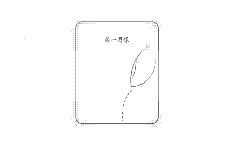
[0069] In the second embodiment, the receiving unit module is further used for sensing an operation area, and the operation area is an area corresponding to operating the image displayed on the display unit module. Such as image 3 As shown, the dotted line indicates the finger operation area.

[0070] The processor unit module is further configured to determine that the display unit module displays the second image in the operation area sensed by the receiving unit module. Such as Figure 4 shown.

[0071] In this embodiment, the receiving unit module is but not limited to a touch screen or a camera.

[0072] In this embodiment, the pattern on the second image includes an application icon, such as a phone call icon, a contact icon, an information icon, a music player icon, a camera icon, and the like. Certainly, the application icon includes pure text, or a combination of text and app...

Embodiment 3

[0075] Embodiment three is basically the same as embodiment two, and its difference is:

[0076] In the third embodiment, the pattern on the first image is partly the same as the pattern on the second image. Such as Figure 5 As shown, there are patterns A, B, C, D, E on the first image. The patterns on the second image are A, B, C.

[0077]


PUM


Abstract

The invention discloses display equipment. The display equipment comprises a display unit module, a receiving unit module and a processing unit module, wherein the display unit module is used for displaying a first image; the receiving unit module is used for receiving an instruction for operating the display equipment; and the processing unit module is used for controlling the display unit module to display a second image according to the instruction which is received by the receiving unit module. The invention also discloses an information processing method of the display equipment. With the adoption of the equipment and the method, an input area corresponding to operation can be automatically determined, and particularly, the position of the second image is determined. The display equipment is easily and simply operated, and is more intelligent.

Description

technical field [0001] The invention relates to the technical field of electronic information, in particular to a display device and an information processing method thereof. [0002] Background technique [0003] The display screens of display devices such as mobile terminals are getting larger and larger, making one-handed operation more and more difficult. Usually, both hands are involved in the operation of the display device, which makes the operation more cumbersome and complicated, takes up more human resources, and reduces the ease of use in terms of humanization. [0004] Plus, the larger size of the display, even with two hands, doesn't seem smart enough. If you want to operate in the current touch area, you often need to follow the operation area displayed on the display screen to operate. For example, if the input box is fixed in a certain position area, the finger needs to be moved to this area for input. Of course, this problem is more prominent when operat...

Claims


Application Information

Patent Timeline
Patent Type & Authority Applications(China)
IPC IPC(8): G06F3/0488
CPCG06F3/04883
Inventor 汤少华
Owner NUBIA TECHNOLOGY CO LTD
Learn More