Solar cell and preparation method thereof

A solar cell and electrode technology, applied in circuits, photovoltaic power generation, electrical components, etc., to avoid PID effects and improve leakage current problems

Active Publication Date: 2013-06-26
AU OPTRONICS CORP
View PDF3 Cites 1 Cited by
  • Summary
  • Abstract
  • Description
  • Claims
  • Application Information

AI Technical Summary

Problems solved by technology

[0004] One of the objectives of the present invention is to provide a solar cell with the emitter inside and its manufacturing method, so as to improve the leakage current problems such as the existing PID effect

Method used


Image

  • Solar cell and preparation method thereof
  • Solar cell and preparation method thereof
  • Solar cell and preparation method thereof

Examples


no. 1 example

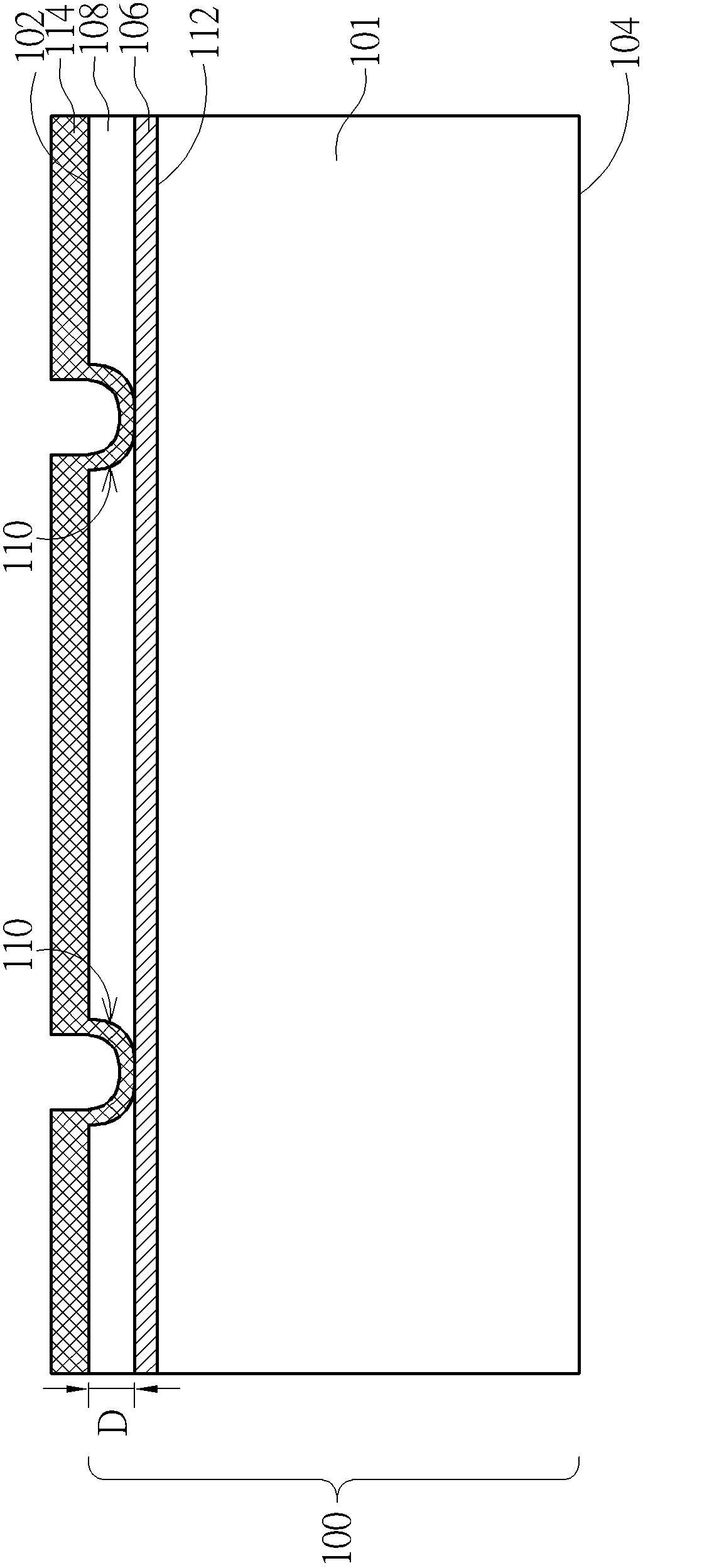
[0055] Similar to the first embodiment, in this embodiment, the substrate 101, the semiconductor layer 108 and the doped region 124 all have the first doping type, while the lightly doped region 106 and the heavily doped region 128 have the second doping type , as opposed to the first doping type. For example, the substrate 101 and the semiconductor layer 108 may have P-type doping, the lightly doped region 106 is N+ type doped, the heavily doped region 128 is N++ type doped, and the doped region 124 is P-type doped , but not limited to this. In other embodiments, the substrate 101 and the semiconductor layer 108 may also have N-type doping, the lightly doped region 106 is P+ type doped, the heavily doped region 128 is P++ type doped, and the doped region 124 is N- type doping.

[0056] Please refer to Figure 10 to Figure 13 It is a process schematic diagram of the third embodiment of the solar cell manufacturing method of the present invention. like Figure 10 As shown,...


PUM


Abstract

The utility provides a solar cell comprising a substrate, a soft doped zone, a semiconductor layer, a first electrode and a second electrode. The substrate is provided with a first surface and a second surface which are arranged oppositely. The soft doped zone is located on the first surface of the substrate, and a doping type of the soft doped zone is opposite to that of the substrate. The semiconductor layer is arranged above the soft doped zone, and the doping type of the semiconductor layer is identical to that of the substrate. The first electrode is located on the first surface of the substrate, and the bottom of the first electrode is cut to align to a port between the soft doped zone and the first surface. The second electrode is arranged on the second surface of the substrate.

Description

technical field [0001] The invention provides a solar cell and a manufacturing method thereof, in particular to a solar cell capable of improving potential induced degradation (PID) conditions and increasing power generation efficiency and a manufacturing method thereof. Background technique [0002] The energy used by humans today mainly comes from oil, but due to the limited oil resources on the earth, the demand for alternative energy has increased day by day in recent years. Among various alternative energy sources, solar energy has become the green energy with the most development potential. [0003] However, limited by high production costs, complex processes, and poor photoelectric conversion efficiency, the development of solar cells still needs further breakthroughs. Please refer to figure 1 , figure 1 It is a structural cross-sectional schematic diagram of an existing solar cell module. The solar cell module 10 includes a solar cell 12 covered by ethylene-vinyl ...

Claims


Application Information

Patent Timeline
Patent Type & Authority Applications(China)
IPC IPC(8): H01L31/0352H01L31/068H01L31/18
CPCH01L31/02168H01L31/022425H01L31/02363H01L31/068H01L31/1804Y02E10/547Y02P70/50H01L31/18
Inventor 胡雁程
Owner AU OPTRONICS CORP
Why Eureka
Try Eureka