Synchronous binding machine drilling device

A technology for a drilling device and a binding machine, which is applied in the field of binding machines, can solve the problems of increased external dimensions, increased costs, and complex overall structure of the binding machine, and achieves the effects of stable transmission, simple structure, and simple and reasonable linkage structure.

Active Publication Date: 2016-05-04
DELI GROUP CO LTD
View PDF7 Cites 0 Cited by
  • Summary
  • Abstract
  • Description
  • Claims
  • Application Information

AI Technical Summary

Problems solved by technology

At present, there is also a fully automatic drilling structure. On the basis of the above structure, the lifting motor and related linkage structure are added to drive the lifting seat for automatic lifting movement. The increased lifting motor and its linkage structure make the overall structure of the binding machine more stable. Become more complex and increase in size, and bring about an increase in cost

Method used


Image

  • Synchronous binding machine drilling device
  • Synchronous binding machine drilling device
  • Synchronous binding machine drilling device

Examples


Embodiment Construction

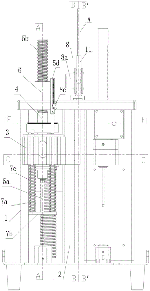
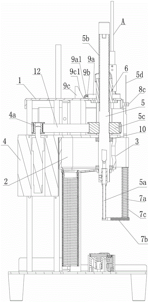
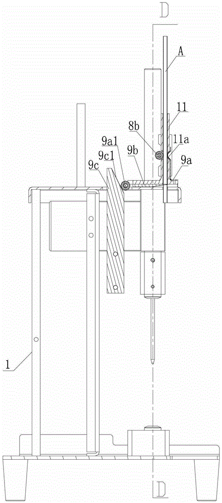
[0039] Such as Figure 1 to Figure 19As shown, a synchronous binding machine drilling device includes a frame 1, a vertical guide post 2, a lifting seat 3, a motor 4, a drilling shaft 5 and a drill 5a, and the vertical guide post 2 is arranged in the frame , the lifting seat 3 is positioned on the vertical guide column 2, the lower end of the drilling rotating shaft 5 is connected to the drill 5a, the motor 4 and the drilling rotating shaft 5 are arranged on the lifting seat 3, the output shaft of the motor 4 is connected to the drilling rotating shaft 5 to rotate, and the drilling The rotating shaft 5 is provided with an external thread section 5b, and the frame 1 is provided with a nut 6 which is screwed to the external thread section 5b.

[0040] The external thread segment 5b is arranged on the upper end of the drilling shaft 5, and the corresponding nut 6 is arranged on the upper part of the frame.

[0041] The rotating shaft of the motor 4 is arranged in parallel with t...


PUM


Abstract

The invention relates to a drilling device of a synchronous type binding machine; and the drilling device comprises a stand, a vertical guide pillar, a lifting seat, a motor, a drilling rotating shaft and a drilling tool, wherein the vertical guide pillar is arranged in the stand; the lifting seat is located on the vertical guide pillar; the lower end of the drilling rotating shaft is connected with the drilling tool; the motor and the drilling rotating shaft are arranged on the lifting seat; an output shaft of the motor is connected with the drilling rotating shaft; the drilling rotating shaft is provided with an external thread section; and the stand is provided with a nut which is connected with the external thread section by threads. The drilling device of the synchronous type binding machine with functions of integral drilling and lifting in a linkage way is realized through linkage of the drilling rotating shaft by one motor, and the drilling device has the advantages of being simple in structure, reasonable in transmission, reduced in volume and lowered in cost.

Description

technical field [0001] The invention relates to a binding machine, in particular to a drilling device for a synchronous binding machine. Background technique [0002] The traditional synchronous binding machine drilling device includes a frame, a manual pressing rod and a main shaft on the frame. The lifting seat is arranged on the main shaft to move up and down. The shaft pin rotates, and the connecting plate then drives the lifting seat to descend along the main shaft. A return spring is arranged on the main shaft between the lifting seat and the frame, and the lifting seat can automatically rise and reset. The above-mentioned structure is a semi-automatic binding machine drilling structure that is manually pressed down so that the drill bit driven by the motor drills down. At present, there is also a fully automatic drilling structure. On the basis of the above structure, the lifting motor and related linkage structure are added to drive the lifting seat for automatic li...

Claims


Application Information

Patent Timeline
Patent Type & Authority Patents(China)
IPC IPC(8): B42B5/08B42B5/02B42B5/00B26F1/16
Inventor 孙兵孙金生
Owner DELI GROUP CO LTD
Why Eureka
Try Eureka