
A riveting structure and automatic binding machine

A technology of riveting and pressing devices, applied in the direction of binding, etc., can solve problems such as inability to achieve complete locking, slippage, and insufficient tightness of binding objects

Active Publication Date: 2019-07-19
DELI GROUP CO LTD
View PDF8 Cites 0 Cited by
  • Summary
  • Abstract
  • Description
  • Claims
  • Application Information

AI Technical Summary

Problems solved by technology

Therefore, the pressure block can not achieve the effect of complete locking only by applying radial force radially to the vertical guide rod of the smooth cylindrical surface of the above-mentioned horizontal brake lever.
During this period, it is easy to cause relative slippage, resulting in the disadvantage that the riveted binding is not tight enough

Method used


Image

  • A riveting structure and automatic binding machine
  • A riveting structure and automatic binding machine
  • A riveting structure and automatic binding machine

Examples


Embodiment Construction

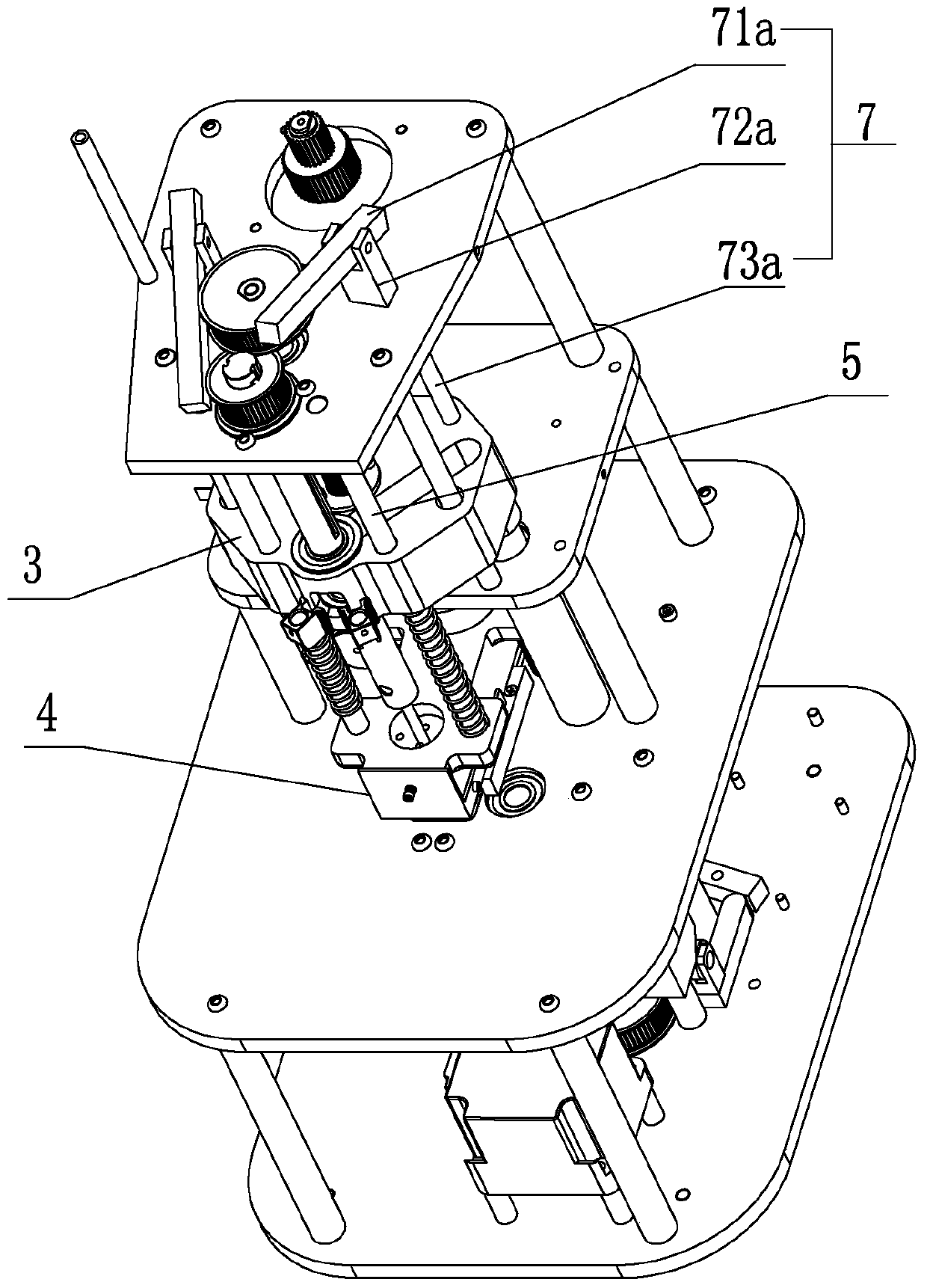
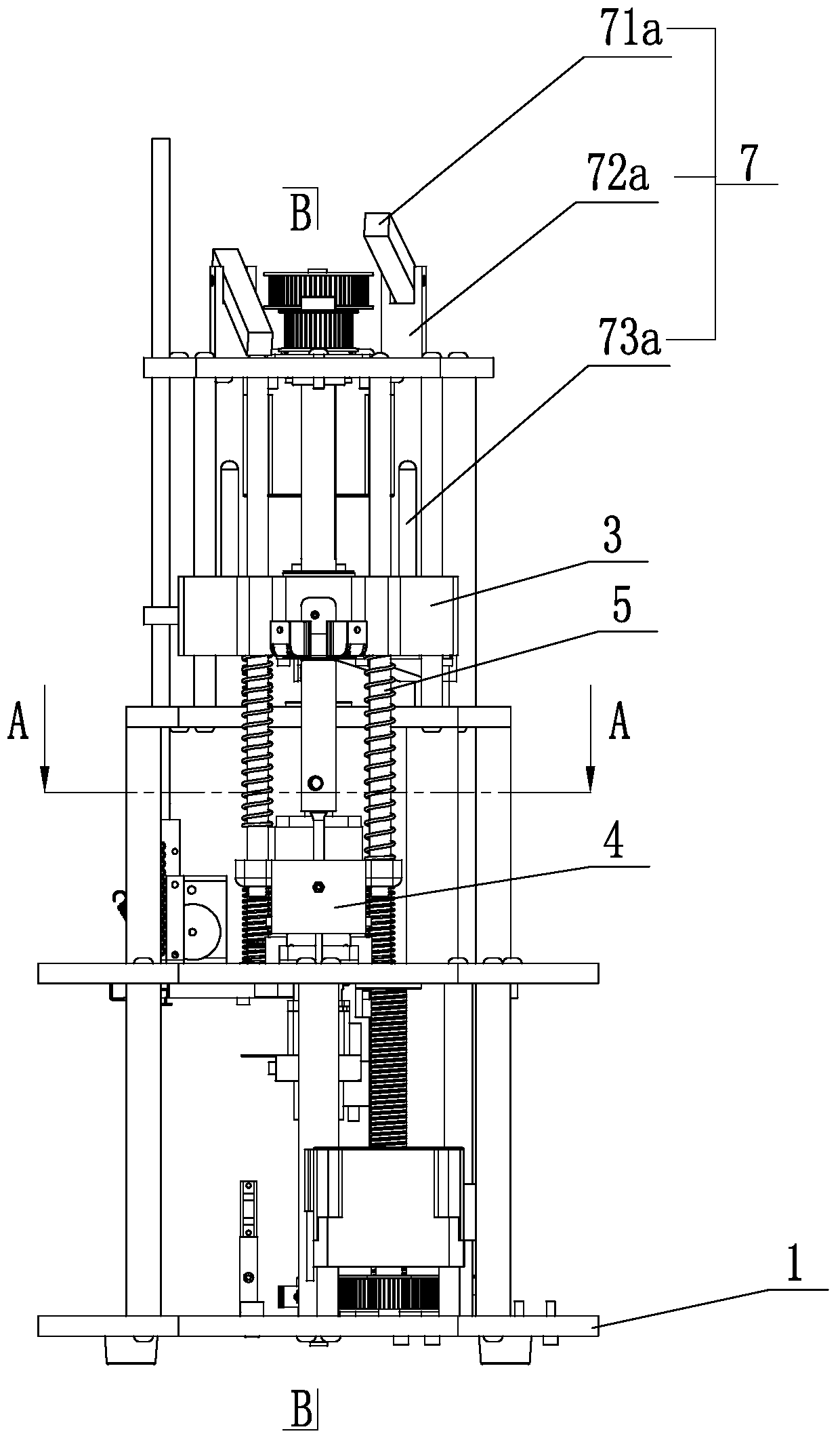
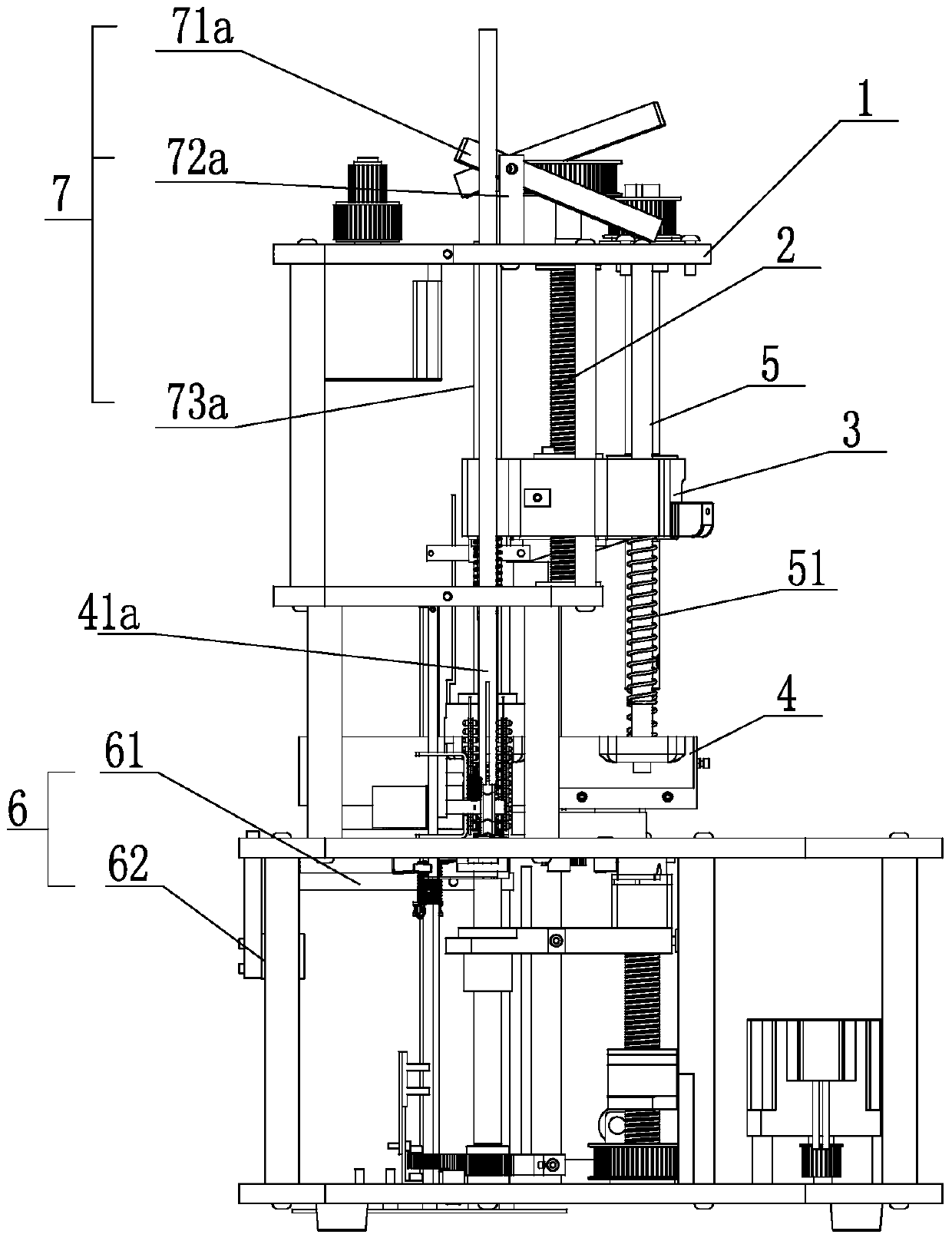
[0052] Such as Figure 1 to Figure 28 As shown, a riveting structure includes a lifting seat 3, a riveting head device 4, and a pressing device 7 in a frame 1. The lifting seat 3 is connected to the riveting head device 4 and can move downward, and the pressing device 7 utilizes the lifting seat 3. Lifting force is converted into downward acting force to press riveting head device 4.

[0053] The frame 1 is provided with a vertical guide column 2, and a lifting seat 3 can be lifted and positioned on the vertical guide column 2.

[0054] The rivet head device 4 includes a paper pressing block 41 for positioning the rivet head.

[0055] The frame 1 is provided with a lifting guide rod 5 , and the lower end of the lifting guide rod 5 is connected with a paper pressing block 41 .

[0056] Frame 1 is provided with follow-up brake device 6, and follow-up brake device 6 is connected lifting seat 3 riveting head device 4 follow-up brakes.

[0057] A riveting structure of the presen...


PUM


Abstract

The invention relates to a riveting structure and a full-automatic binding machine. The riveting structure comprises a rack, a lifting seat, a head riveting device and a compressing device are arranged in the rack, the lifting seat is connected with the head riveting device and can act downwards, and the compressing device compresses the head riveting device through downward acting force converted from rising force of the lifting seat. According to the riveting structure and the full-automatic binding machine, a paper pressing block is completely locked through the downward acting force converted from the rising force of the lifting seat before riveting, and the advantages of being simple in structure and reasonable in transmission are achieved.

Description

technical field [0001] The invention relates to a binding machine, in particular to a riveting structure and an automatic binding machine. Background technique [0002] The traditional automatic punching and hot riveting binding machine includes an automatic punching device on the upper part of the machine and a hot riveting device on the lower part of the machine, which realizes automatic punching of the bound object, measuring and cutting and sending the riveting tube, and the upper and lower ends of the hot riveting tube after being inserted into the hole Hot riveting binding and other actions, the traditional automatic punching hot riveting binding machine has disadvantages such as complex interlocking structure and unstable binding quality. Wherein the paper pressing device includes a vertical guide column, a lifting seat and a paper pressing block arranged in the frame, the lifting seat is positioned on the vertical guiding post, and the paper pressing block is positio...

Claims


Application Information

Patent Timeline
Patent Type & Authority Patents(China)
IPC IPC(8): B42B5/00B42B5/02
CPCB42B5/00B42B5/02
Inventor 孙兵
Owner DELI GROUP CO LTD
Learn More