linear actuator

A technology of linear actuators and wire teeth, which is applied to transmissions, transmission parts, belts/chains/gears, etc., and can solve problems such as complicated installation, many gear parts, and difficulty in further reducing the volume

Active Publication Date: 2015-11-25
JUF MOTOR
View PDF7 Cites 0 Cited by
  • Summary
  • Abstract
  • Description
  • Claims
  • Application Information

AI Technical Summary

Problems solved by technology

[0004] According to the above-mentioned two linear actuators disclosed above, the Taiwan patent No. M369950 "push rod structure" needs to be driven in the middle of a transmission gear set composed of a plurality of pinions to achieve linear movement of the detent and The function of the action micro switch, so the gearbox has a large volume
Although Taiwan's new patent No. M247738 "Linear Transmission Mechanism" does not use a transmission gear set, the micro switch is directly built into the dust-proof sleeve, but this will also increase the volume of the dust-proof sleeve
Therefore, the disadvantages of the linear actuator of the above-mentioned previous proposals are that there are many gear parts, the installation is complicated, and the volume is difficult to further reduce. All of these are the linear actuators that still need to be improved.

Method used


Image

  • linear actuator
  • linear actuator
  • linear actuator

Examples


Embodiment Construction

[0025] The horizontal and straight annular wire teeth mentioned in the following embodiments of the linear actuator of the present invention indicate the horizontal or vertical direction drawn in the drawings, and the purpose is only to provide convenience for review, not to limit the scope of the present invention.

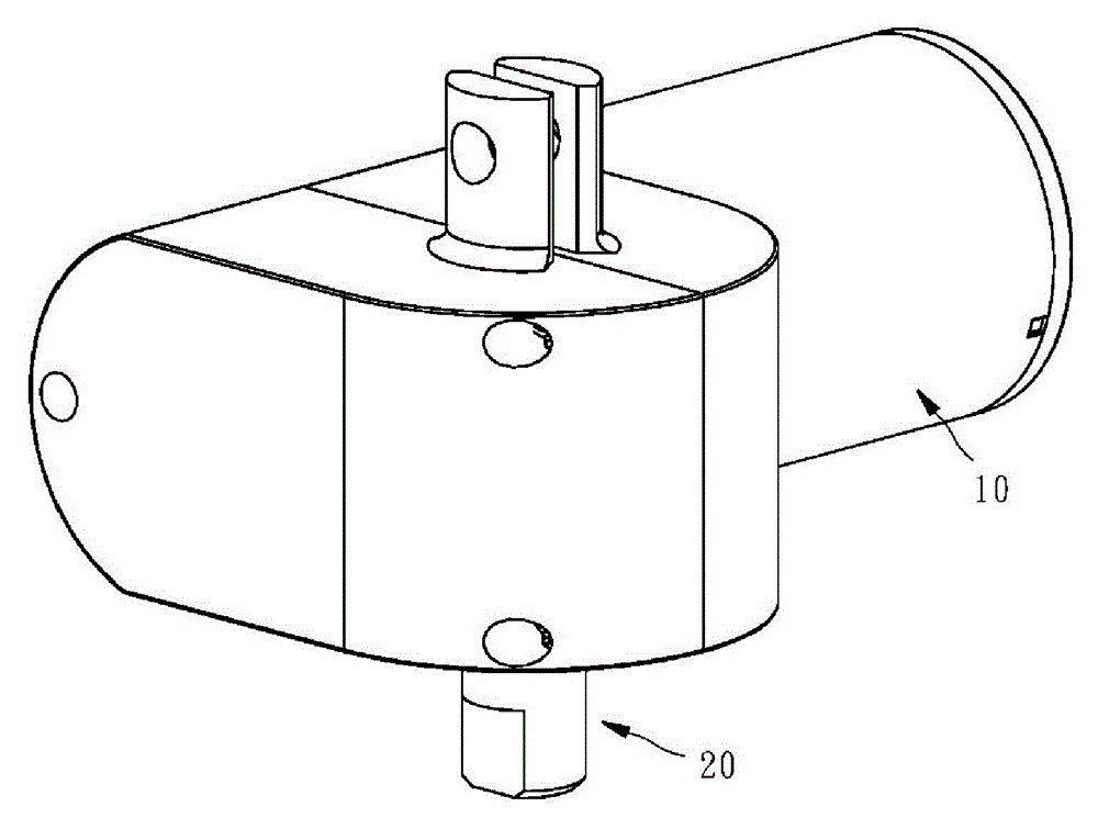
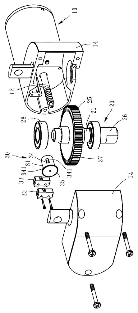
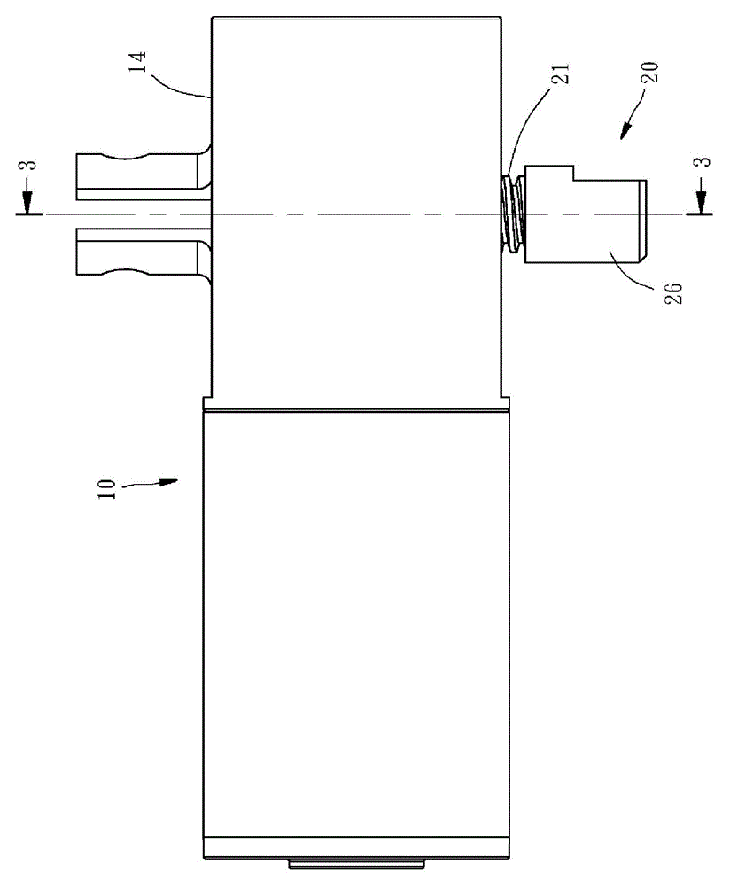
[0026] See first Figure 1 to Figure 4 As shown, the linear actuator of the first embodiment provided by the present invention includes a motor 10, a displacement unit 20, and a stroke control unit 30; wherein the motor 10 has a spindle 12, and a ring is arranged on the spindle 12 The outer gearbox housing 14, in this embodiment, the spindle 12 is a worm. This displacement unit 20 has a worm wheel 25, an output shaft 21 and a stopper 26, and one side of the body of the worm wheel 25 (not the worm gear) is provided with a horizontal annular wire tooth (arranged on the upper surface of the worm wheel 25), The circular thread tooth of this embodiment is a spiral th...


PUM


Abstract

The invention relates to a linear actuator which comprises a motor, a displacement unit and a travel control unit. The motor is provided with a mandrel; the displacement unit comprises a worm gear and a rotating shaft; one position of a worm gear body is provided with a ring-shaped spiral thread or external helix thread; and the travel control unit is provided with at least one transmission parts and at least one microswitch, wherein the at least one transmission part is connected with the spiral thread or external helix thread of the displacement unit and is driven by the spiral thread or external helix thread to synchronous rotate for actuating action of enabling the at least one microswitch to be started or shut down. By the technical scheme, through the design of forming the spiral thread or external helix thread at one position of the worm gear body, can control the operation of the travel control unit can be controlled.

Description

technical field [0001] The invention relates to an actuator, in particular to a linear actuator with compact volume. Background technique [0002] Devices using linear transmission strokes (hereinafter referred to as linear actuators) are used for position adjustment in massage chairs, electric chairs, electric hospital beds, treadmills, folding beds, furniture, and lifting mechanisms. It is a very common technology. For the starting position and end position of the linear transmission stroke, more than one micro switch must be used as the control of the forward and return strokes of the linear stroke, and the micro switches are respectively installed at the starting point position and the final point position of the linear path. When the linear actuator is displaced by the forward stroke of the linear transmission and touches the micro switch at the end position, the transmission rod can be restricted from moving to the forward stroke; When the micro switch at the starting...

Claims


Application Information

Patent Timeline
Patent Type & Authority Patents(China)
IPC IPC(8): F16H37/00F16H57/039
Inventor 郑智弘黄伟民
Owner JUF MOTOR
Why Eureka
Try Eureka