Table-type cloth cutting machine with sliding guide rail

A cutting machine and guide rail technology, applied in the field of cutting machines, can solve the problem of inaccurate cutting and achieve the effect of solving the effect of inaccurate cutting angle

Inactive Publication Date: 2013-07-03
NINGBO EASTSUN TEXTILES
View PDF6 Cites 7 Cited by
  • Summary
  • Abstract
  • Description
  • Claims
  • Application Information

AI Technical Summary

Problems solved by technology

[0003] Aiming at the deficiencies in the prior art, the present invention provides a desktop cloth cutting machine with slideable guide rails. The cutting machine can accurately cut out cloth with different required inclination angles, and solves the problem of inaccurate cutting when cutting inclined cloth in the past. shortcoming

Method used


Image

  • Table-type cloth cutting machine with sliding guide rail
  • Table-type cloth cutting machine with sliding guide rail
  • Table-type cloth cutting machine with sliding guide rail

Examples


Embodiment 1

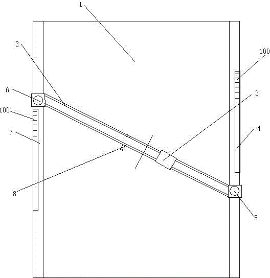
[0015] Embodiment 1: see figure 1 , Figure 7 Shown: a cutting machine, including a bed 1, a guide rail 2, a first slide 7 and a second slide 4 on both sides of the bed 1, between the first slide 7 and the second slide 4 there is a The guide rail 2 that moves on the first slideway 7 and the second slideway 4. The guide rail 2 includes a first guide rail 31 and a second guide rail 32, which can slide relatively between the first guide rail 31 and the second guide rail 32, and the length of the entire guide rail 2 can be adjusted. and on the second slideway 4, so the guide rail 2 can present a certain angle on the two slideways. There is a first fixing part 8 on the first guide rail 31 , and the first fixing part 8 can fix the first guide rail 3 on the second guide rail 32 . The first fixing member 8 can be a simple screw fixing or other fixings. The length of the guide rail 2 can be determined after the first fixing member 8 is fixed. The second fixing member 6 fixes the f...

Embodiment 2

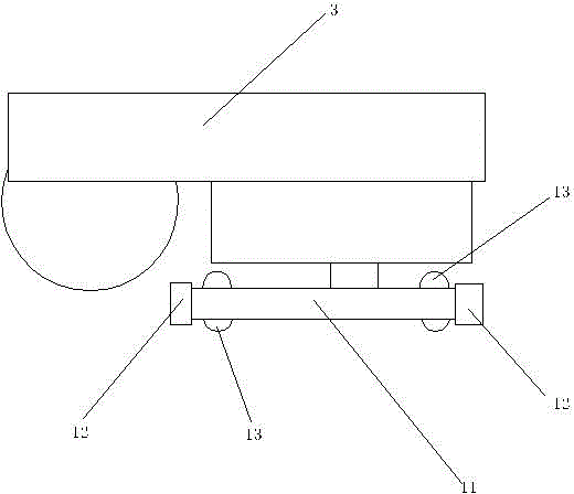
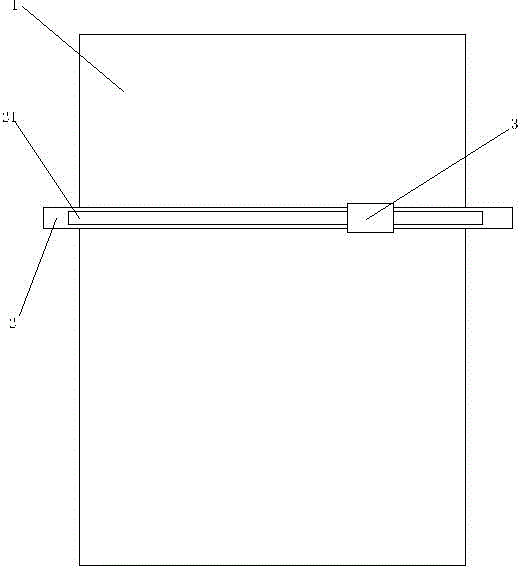
[0017] Example 2: see image 3 , Figure 4 , Figure 5 Shown: a cutting machine, including a guide rail 2, a cutter 3 that can move on the guide rail 2, a first conveying device 21 is arranged inside the guide rail 2, and a second conveying device 21 that matches the first conveying device 21 is arranged on the cutter 3 Conveyor 24. Rely on the first conveying device 21 on the guide rail to drive the second conveying device 24 on the cutter 3 like this, allow the cutter to move. The first transmission device 21 is a first worm 22 and a second worm 28 , and the second transmission device 24 is a first gear 41 cooperating with the first worm 22 and the second worm 28 . The first worm screw 22 and the second worm screw 28 are on both sides in the track 2, and the first gear 41 on the cutter fits with the first worm screw 22 and the second worm screw 28 respectively, and starts the first worm screw 22 and the second worm screw 28 simultaneously, The first gear 41 on the cutter...


PUM


Abstract

A table-type cloth cutting machine with a sliding guide rail belongs to the field of textile machinery. The cloth cutting machine comprises a lathe bed and a guild rail, wherein a first slideway and a second slideway are arranged on the two sides of the lathe bed; the guide rail is arranged between the first slideway and the second slideway in a sliding manner; the guide rail comprises a first guide rail and a second guide rail; the second guide rail which can slide relatively is arranged on the first guide rail; a first fixing piece used for fixing the first guide rail on the second guide rail is arranged on the first guide rail; a second fixing piece used for fixing the first guide rail on the first slideway is arranged on the first guide rail; the first guide rail can rotate relative to the second fixing piece; a third fixing piece used for fixing the first guide rail on the second slideway is arranged on the second guide rail; and the second guide rail can rotate relative to the third fixing piece. Compared with the prior art, the cutting machine can cut out cloth of different inclination angles accurately according to different requirements, and primarily solves the problem that a previous cutting machine is poor in accuracy when cutting an inclination cloth material.

Description

technical field [0001] The invention belongs to the field of textile machinery, in particular to a cutting machine. Background technique [0002] Cutting machine is a very important textile machinery in the textile industry. At present, there are many kinds of cutting machines, and various semi-automatic and fully automatic cutting machines have appeared, but desktop cutting machines are still the necessary cutting machines for most textile enterprises. Desktop cutting machine, also known as desktop cutting machine, is easy to operate, simple in structure and neat in cutting. Widely used in clothing, textile, leather, plastic leather, and other industries to cut cotton, linen, synthetic leather, silk, knitting and other raw materials, and can also cut carpets, towels, bed sheets, plastic films and other materials. The working principle of the desktop cutting machine is that there is a guide rail on the table, the cloth is placed on the guide rail, and the cloth is cut off ...

Claims


Application Information

Patent Timeline
Patent Type & Authority Applications(China)
IPC IPC(8): D06H7/10
Inventor 周秋月
Owner NINGBO EASTSUN TEXTILES
Why Eureka
Try Eureka