Rolling mill with optimized determination of cutting points

a cutting point and rolling mill technology, applied in the field of rolling mill operation, can solve the problems of reducing the productivity and efficiency of the rolling mill, the method of the state of the art is complicated and inexact, and achieve the effect of minimising the oversize over the minimum length

Active Publication Date: 2017-10-03
PRIMETALS TECH GERMANY
View PDF3 Cites 2 Cited by
  • Summary
  • Abstract
  • Description
  • Claims
  • Application Information

AI Technical Summary

Benefits of technology

[0006]It is an object of the present invention to provide a method of operation for a rolling mill for rolling a billet which minimises the oversize over the minimum length.
[0013]In a preferred embodiment of the method of operation, when determining the cutting commands, a thermal shrinkage of the sections of the rod due to the difference between a finishing temperature and a normal temperature is taken into account. Therefore, higher accuracy in the determination of the predetermined length can be achieved.
[0031]Due to this embodiment, the total length of the rod determined by calculation can be determined very accurately.
[0034]Preferably, cutting commands for cropping the intermediate product are triggered on the one hand by the detection of the head end of the intermediate product by the front laser measurement device and on the other hand based upon an instantaneous length of the intermediate product determined by integrating the speed of the intermediate product detected by the front laser measurement device in combination with an expected total length of the intermediate product determined by calculation. Due to this embodiment, the cropping of the head end and of the tail end of the intermediate product may be achieved very precisely. The expected total length of the intermediate product may be determined from the length of the billet taking into account the total reduction in cross-section achieved in the front section of the rolling mill.

Problems solved by technology

The method of the state of the art is complicated and inexact.
The additional length reduces the productivity and efficiency of the rolling mill.

Method used


Image

  • Rolling mill with optimized determination of cutting points
  • Rolling mill with optimized determination of cutting points
  • Rolling mill with optimized determination of cutting points

Examples


Embodiment Construction

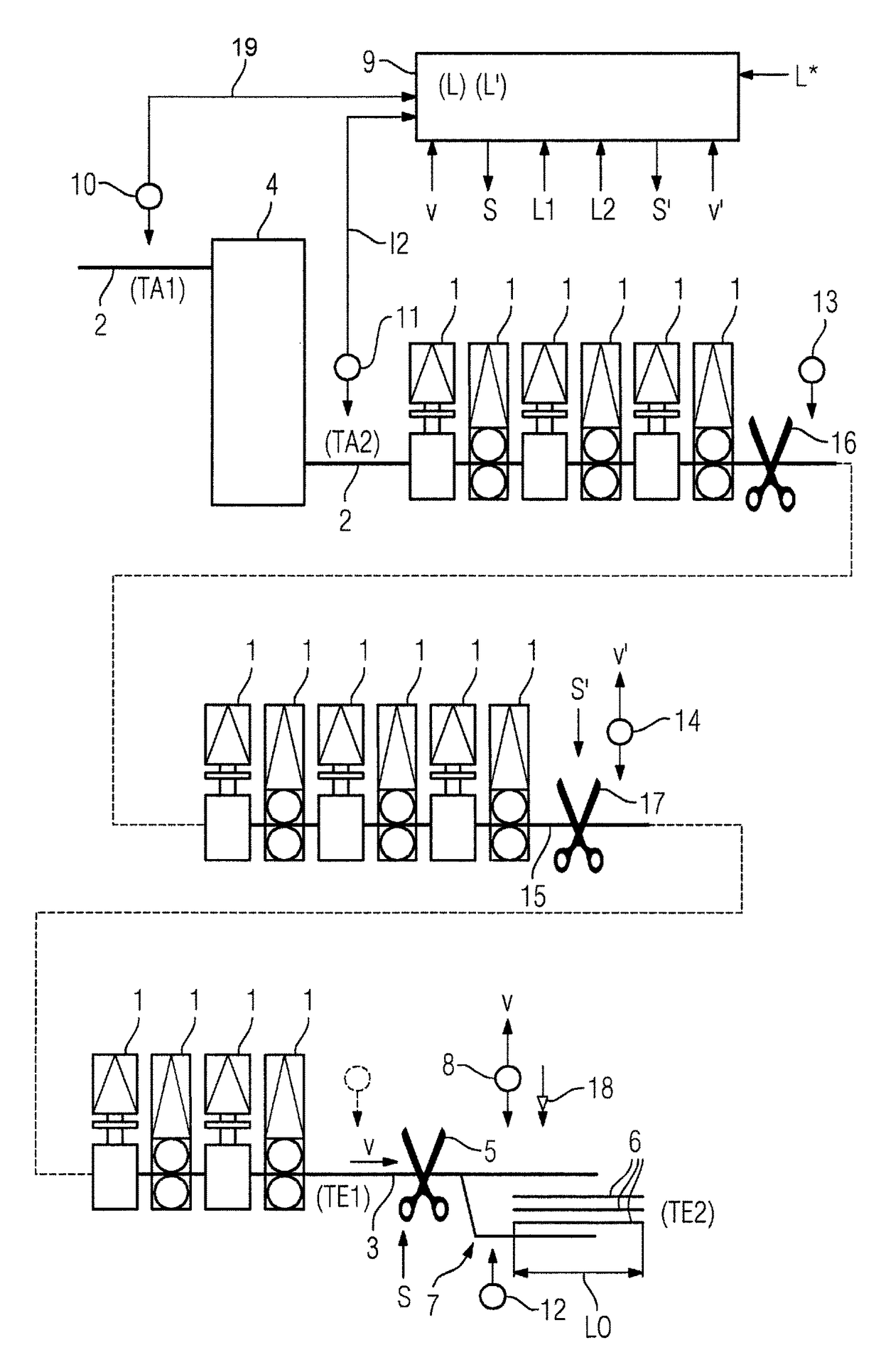
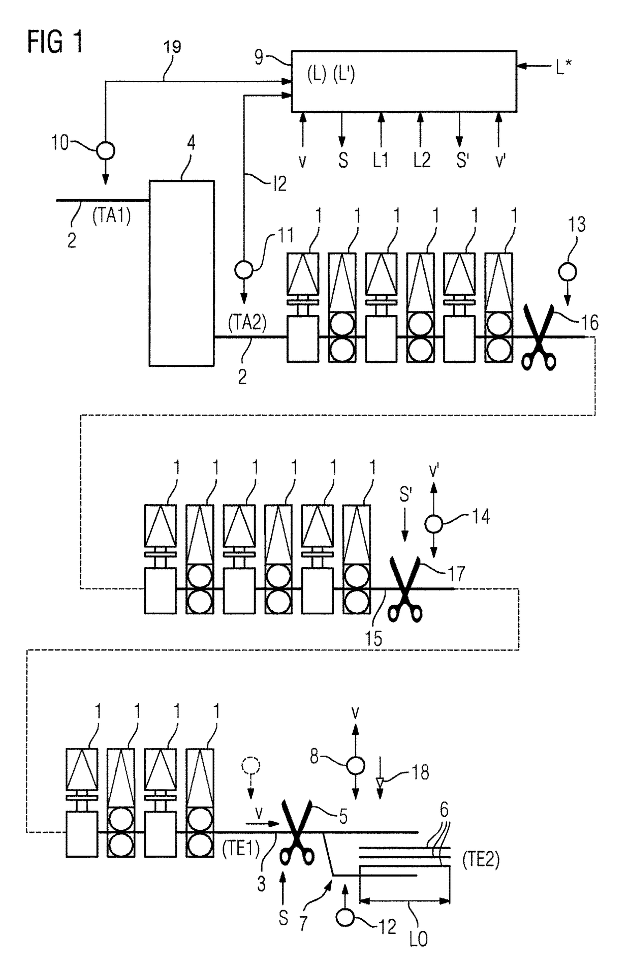
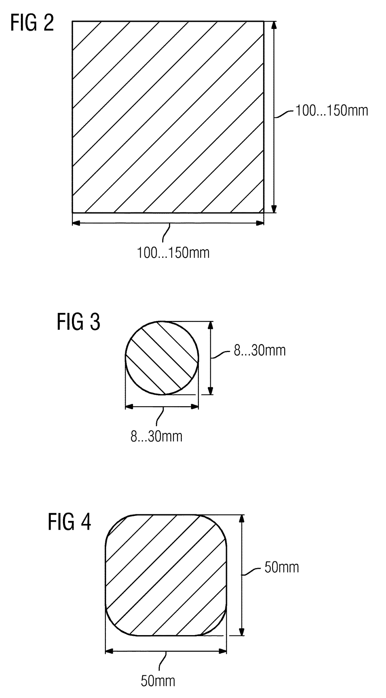
[0040]As shown in FIG. 1, a rolling mill comprises a plurality of rolling stands 1. The rolling stands 1 may be configured, as shown in FIG. 1, alternately as horizontal rolling stands and vertical rolling stands. A billet 2 shall be rolled in the rolling mill of FIG. 1. A billet 2 is a rolling product prior to rolling in the rolling mill. It usually has a rectangular or circular cross-section, the width of the product and the height or thickness of the product being roughly equal. For example, a billet 2 may have, as shown in FIG. 2, a width in the range between 100 and 150 mm and a height or thickness also in the range between 100 and 150 mm. The width of the product and the height or thickness of the product may be equal. This is, however, not necessarily the case.

[0041]The billet 2 is rolled in rolling stands 1 of the rolling mill step-by-step to a rod 3. A rod 3 is a product after being rolled in the rolling mill, i.e. which has exited the last rolling stand 1 of the rolling mi...


PUM

PropertyMeasurementUnit
thicknessaaaaaaaaaa
thicknessaaaaaaaaaa
heightaaaaaaaaaa

Abstract

A billet (2) is rolled to a rod (3) in a rolling mill. The rod (3) exits the rolling mill with a finishing temperature (TE1). A rear laser measurement device (8) arranged downstream of the rolling mill detects the head end and the speed (v) of the rod (3). The detected speed (v) of the rod (3) is integrated to its length and an instantaneous length (L) of the rod (3) is determined. Dependent on the determined instantaneous length (L) of the rod (3), cutting commands (S) to a rear shears (5) arranged downstream of the rolling mill are provided for cutting the rod (3) in sections (6) of predetermined length (L0). The sections (6) of the rod (3) are cooled down in a cooling bed (7).

Description

TECHNICAL FIELD OF THE INVENTION[0001]The present invention concerns a method of operation of a rolling mill for rolling a billet,[0002]wherein the billet is rolled in the rolling mill to a rod, said rod exiting the rolling mill with a finishing temperature,[0003]wherein sections of the rod are cooled down in a cooling bed.BACKGROUND OF THE INVENTION[0004]In rolling mills of the above-mentioned type, billets are rolled to rods. Downstream of the rolling mill, shears are arranged. By means of the shears, the rolled rod is cut into sections of predetermined length. The total length of the rolled rod usually is determined by the initial length of the billet, taking into consideration the reductions in cross-section occurring in the rolling stands of the rolling mill. Additionally, sections separated by crop cuts within the rolling mill are taken into account. The accumulated length of the rod which has at a certain point of time exited the rolling mill usually is determined by the circ...

Claims


Application Information

Patent Timeline
Patent Type & Authority Patents(United States)
IPC IPC(8): B21B37/72B21B15/00B21B1/16B21B38/00B23D36/00
CPCB21B37/72B21B1/16B21B15/0007B21B38/00B23D36/0016B21B2015/0014B21B2261/12B21B2275/06B21C51/00
Inventor LING, YUNRICHES, PAUL BARRY
Owner PRIMETALS TECH GERMANY
Why Eureka
Try Eureka