
Golf Club Fitting Assembly

Inactive Publication Date: 2010-02-11
YU SHUJEN +1
View PDF24 Cites 75 Cited by
  • Summary
  • Abstract
  • Description
  • Claims
  • Application Information

AI Technical Summary

Benefits of technology

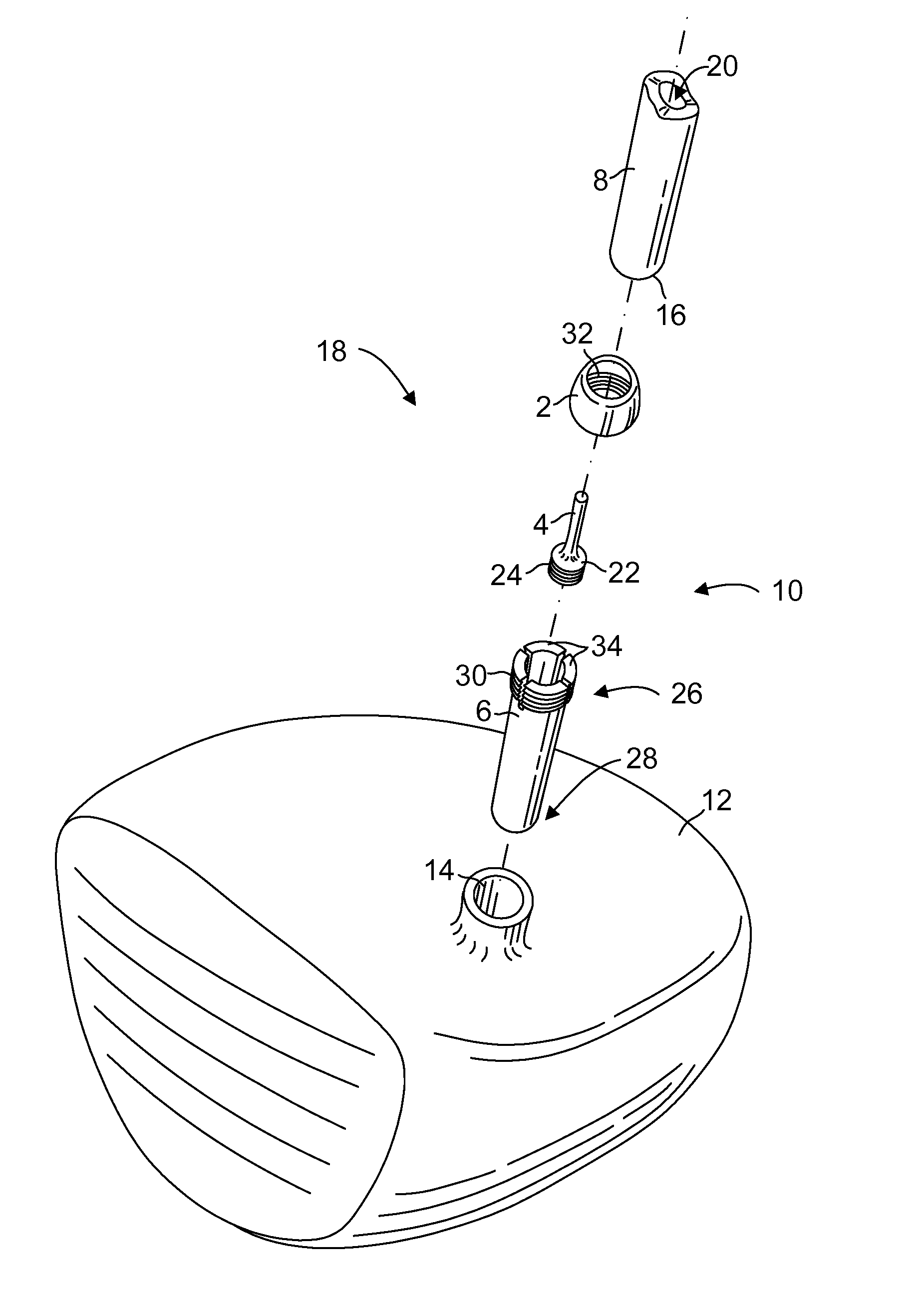
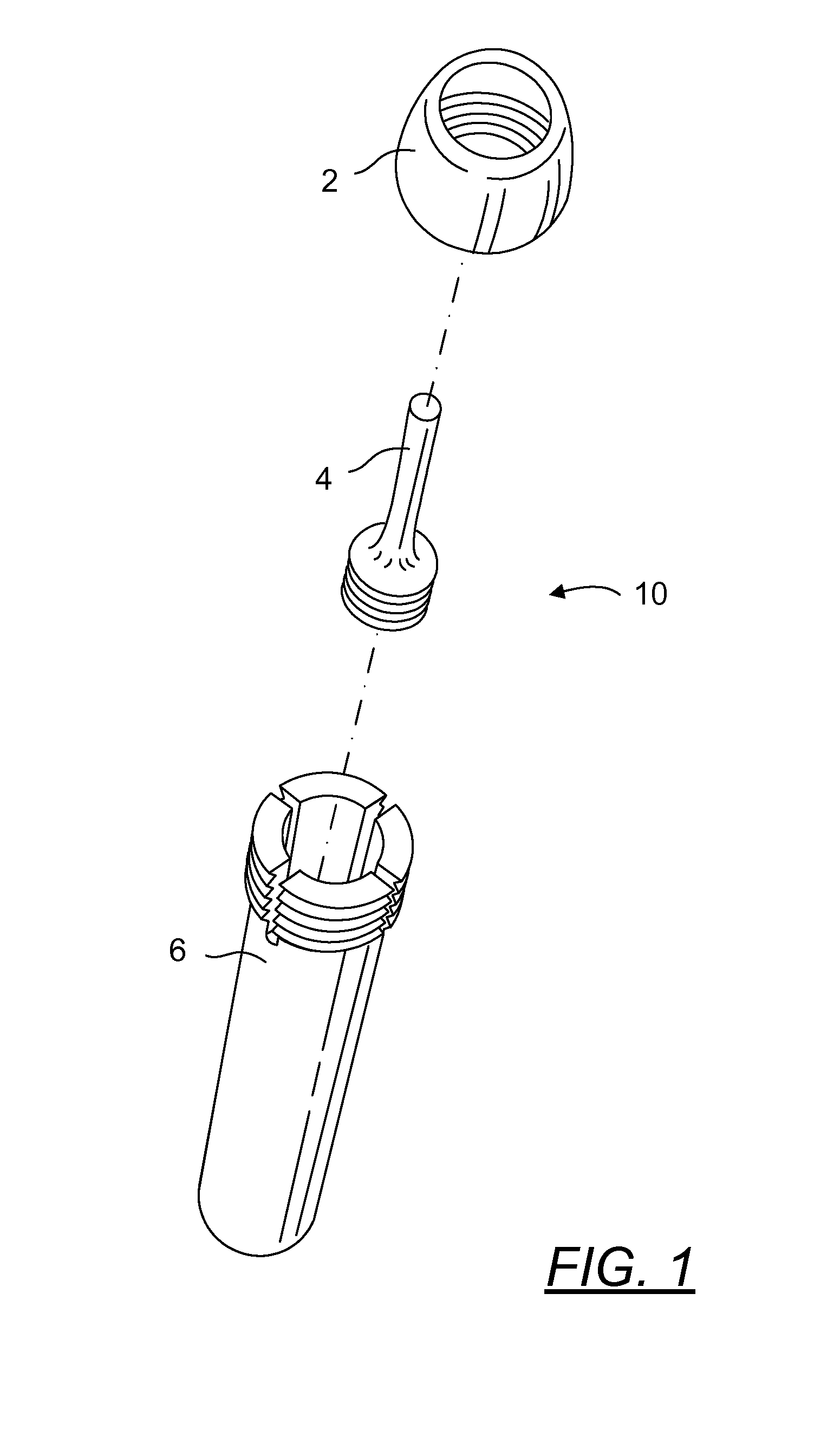
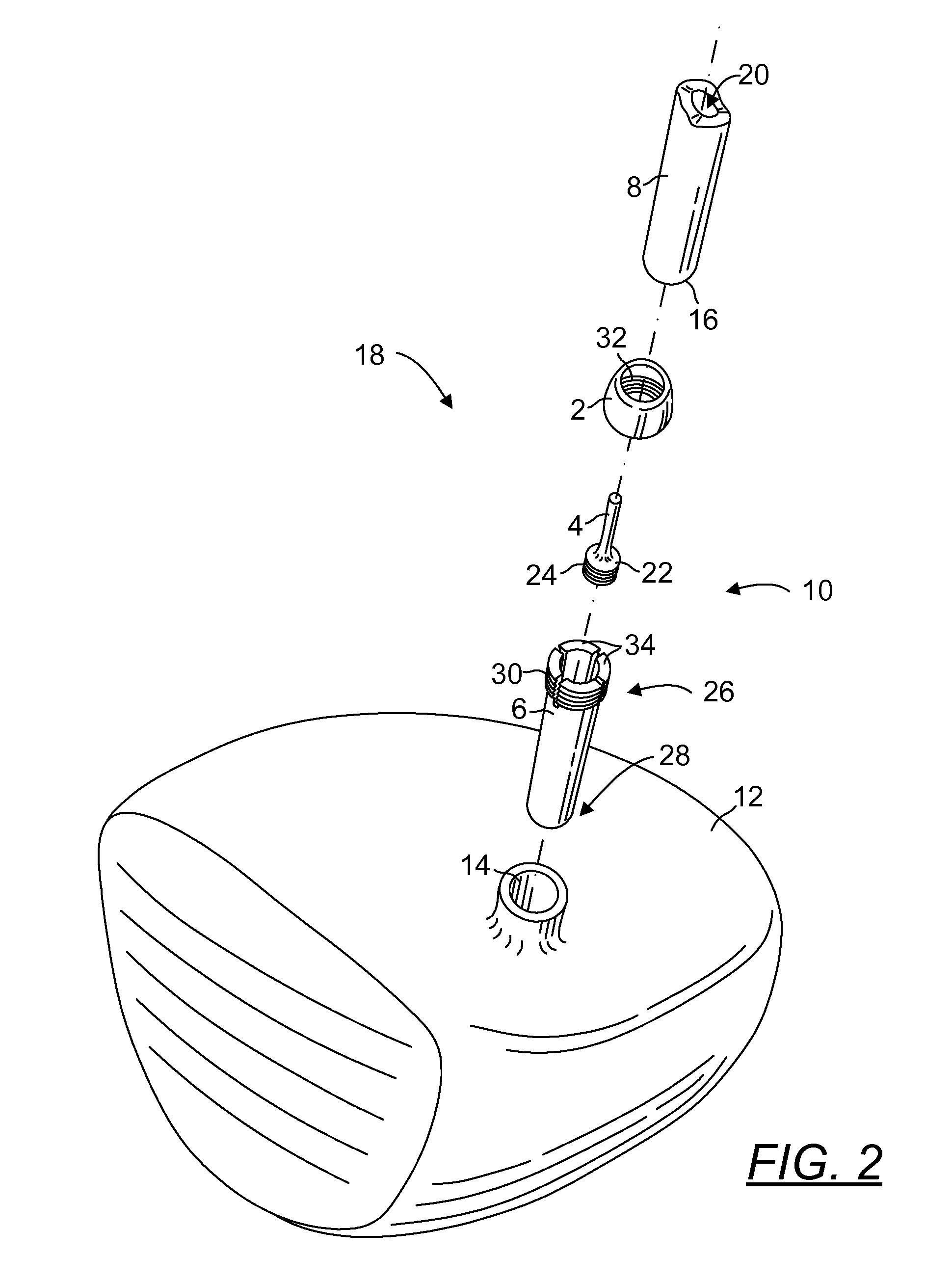
[0008]It is an object of this invention to provide an interchangeable golf club fitting assembly that minimizes the length of shaft that is decreased when mounted and connected to a club head.
[0018]It is a further object of the present invention to provide a universal interchangeable golf club fitting assembly that does not alter the playability characteristics of the shaft or club head.

Problems solved by technology

While some of these devices have gained popularity, they have not been successful in minimizing the impact upon playability of the golf club assembly and providing substantially the same feel and characteristics of a manufactured assembly of the same club head and shaft.
Prior art devices have also not been successful in providing a truly universal golf club fitting that may be used with any manufacturer's club head or shaft, including irons, woods, putters, “rescue clubs,” drivers and the like, without altering shaft characteristics.
The drawback of the prior art is that interchangeable golf fitting installation requires the shaft to be cut down and / or inserted into the club head.
This loss of shaft length negatively affects the shaft characteristics.

Method used


Image

  • Golf Club Fitting Assembly
  • Golf Club Fitting Assembly
  • Golf Club Fitting Assembly

Examples


Embodiment Construction

Definitions

[0045]As used in this specification, wood means a club meant to drive the ball a great distance down the fairway towards the hole, generally having a large head and a long shaft for maximum club speed. Originally made of wood, contemporary ‘woods’ are made from different metals, but called ‘woods’ to denote the general shape and their intended use on the golf course. Woods are also known in the golf industry as “driver”, “1 wood”, “fairway woods”, “utility woods,” and the like.

[0046]As used in this specification, Irons are golf clubs with a flat angled face and a shorter shaft than a wood, designed for shots approaching the green or from more difficult lies such as the rough, through or over trees, or the base of hills. Irons feature thin club heads and grooved faces and a relatively narrow sole, usually somewhere between 16° and 65°. Originally made from cast iron, contemporary irons are made of metal such as steel.

[0047]As used in this specification, driver means the nu...


PUM


Abstract

This invention relates to golf club fitting devices and more particularly, to a novel golf club fitting assembly designed to interchangeably connect a shaft and club head.

Description

FIELD OF THE INVENTION[0001]This invention relates to golf club fitting devices and more particularly, to a novel golf club fitting assembly designed to interchangeably connect a shaft and club head.BACKGROUND[0002]Various golf club fittings are known in the art to interchangeably connect a shaft and club head. Prior art attempts to propose a solution include devices and methods disclosed in US20070078026A1, US20060281575A1, US20050096148A1, U.S. Pat. No. 7,115,046, U.S. Pat. No. 7,083,529, U.S. Pat. No. 5,863,260, U.S. Pat. No. 7,144,332, U.S. Pat. No. 6,475,097, U.S. Pat. No. 5,452,890, WO9934882A1, US20050101401A1, U.S. Pat. No. 7,207,897, US20070117645A1, EP0634194A3, U.S. Pat. No. 6,890,269, U.S. Pat. No. 7,226,364, WO9524243A1, WO9944697A1, U.S. Pat. No. 5,624,330, U.S. Pat. No. 5,181,720, and US20040132540A1. The specification of each of these patents is incorporated by reference into this specification.[0003]While some of these devices have gained popularity, they have not b...

Claims


Application Information

Patent Timeline
IPC IPC(8): A63B53/02
CPCA63B2053/027A63B53/02A63B53/027A63B60/54
Inventor YU, SHUJENCHO, WILLIAM
Owner YU SHUJEN
Learn More