
Circular wood block cutting and forming equipment for machining

A technology for molding equipment and wood blocks, applied in sawing equipment, wood processing equipment, circular saws, etc., can solve problems such as inability to fix, sawdust pollution, wood waste, etc., and achieve the effect of saving manpower and improving performance

Pending Publication Date: 2022-04-08
刘会妹
View PDF7 Cites 1 Cited by
  • Summary
  • Abstract
  • Description
  • Claims
  • Application Information

AI Technical Summary

Problems solved by technology

[0005] In order to overcome the shortcomings of being unable to fix, poor cutting effect, waste of wood, and pollution of sawdust, the technical problem of the present invention is to provide a round wood block cutting and forming equipment for processing that can improve automatic cutting, optimize cutting accuracy and reduce waste.

Method used


Image

  • Circular wood block cutting and forming equipment for machining
  • Circular wood block cutting and forming equipment for machining
  • Circular wood block cutting and forming equipment for machining

Examples


Embodiment 1

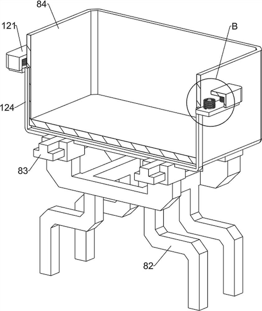
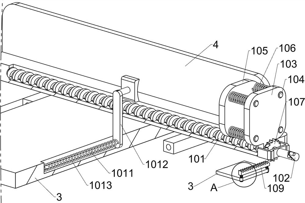
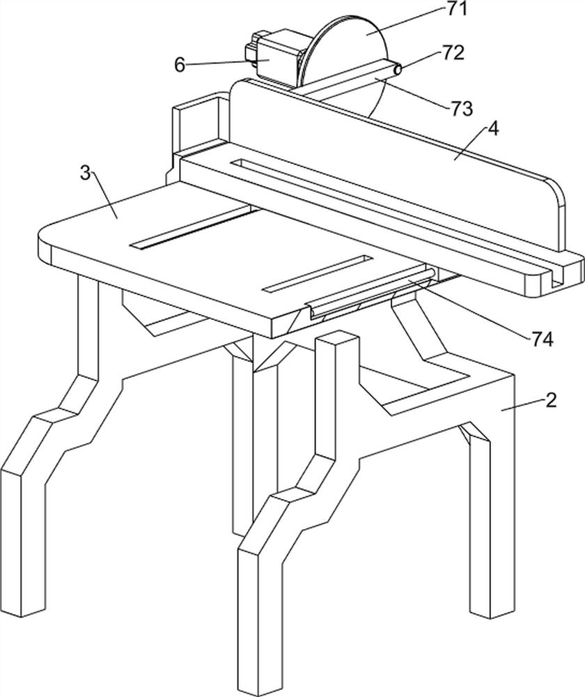
[0029] A kind of round wood block cutting and forming equipment for processing, such as Figure 1-Figure 3 As shown, it includes a base 1, a first support frame 2, a workbench 3, a placement plate 4, a saw blade 5, a motor 6, a reciprocating assembly 7 and a collection assembly 8, and the top of the base 1 is provided with a first support frame 2, the first A workbench 3 is provided on the top of a support frame 2, a sliding plate 4 is provided on the right side of the workbench 3, a saw blade 5 is provided on the left rear side of the workbench 3, and a motor 6 is provided on the right rear side of the top of the base 1. A reciprocating assembly 7 is connected between the motor 6 and the placing plate 4 , and a collection assembly 8 is provided on the rear side of the top of the base 1 .

[0030] First place the round wood on the placement board 4, the starting motor 6 cooperates with the reciprocating motion assembly 7 to drive the placement board 4 to move to the left, and ...

Embodiment 2

[0036] On the basis of Example 1, such as Figure 4-Figure 9 As shown, the fixed assembly 9 is also included, and the fixed assembly 9 includes a first support rod 91, a second guide rod 92, a second support rod 93, a roller 94 and a first spring 95, and the left side of the placement plate 4 is arranged symmetrically front and back. The first support rod 91, the first support rod 91 is equipped with a second guide rod 92 symmetrically sliding up and down, the second guide rod 92 is equipped with a second support rod 93, and the second support rod 93 is of a rotating type. Rollers 94 are provided, and first springs 95 are symmetrically connected between the first support rod 91 and the second support rod 93 , and the first springs 95 are respectively sleeved on the second guide rods 92 .

[0037] When people need to install the round timber on the placement board 4, first the second support rod 93 is pulled to the left, the first spring 95 is compressed, and after the round ti...


PUM


Abstract

The invention relates to cutting forming equipment, in particular to circular wood block cutting forming equipment for machining. According to the circular wood block cutting forming equipment for machining, automatic cutting can be improved, the cutting precision is optimized, and waste is reduced. According to the technical scheme, the circular wood block cutting and forming equipment for machining comprises a base and a first supporting frame, and the first supporting frame is arranged at the top of the base; the workbench is arranged at the top of the first supporting frame; and the saw blade is rotationally arranged on one side of the workbench. Round wood is placed on a placing plate, a motor is started to cooperate with a reciprocating motion assembly to drive the placing plate to move leftwards, the placing plate and the round wood move leftwards to make contact with a saw blade rotating at a high speed, the saw blade cuts the round wood, and cut round wood blocks fall into a collecting assembly to be collected. The effects of improving automatic operation and saving manpower are achieved.

Description

technical field [0001] The invention relates to a cutting and forming equipment, in particular to a cutting and forming equipment for round wooden blocks for processing. Background technique [0002] Wood is the lignified tissue of plants capable of secondary growth, such as trees and shrubs. After the primary growth of these plants ends, the vascular cambium in the rhizome starts to move, developing bast outward and wood inward. Wood is a general term for plant tissues that develop inward from the vascular cambium, including xylem and Thin-walled rays. Wood plays a great supporting role in human life. According to the different properties and characteristics of wood, people use them in different ways. Cutting is a physical action. Cutting in a narrow sense refers to cutting objects (such as food, wood and other objects with low hardness) with sharp tools such as knives; cutting in a broad sense refers to using tools, such as machine tools, flames, etc. to make objects ...

Claims


Application Information

Patent Timeline
Patent Type & Authority Applications(China)
IPC IPC(8): B27B5/22B27B5/29
Inventor 刘会妹
Owner 刘会妹
Learn More