Bipolar screw-in lead

a technology of bipolar active fixation and screw-in leads, which is applied in the direction of external electrodes, internal electrodes, therapy, etc., can solve the problems of high cost, high cost, and complex performance of screw-in leads, and achieves high friction, improve acute and chronic electrode stabilization, and save time in having

Active Publication Date: 2010-11-23
PACESETTER INC
View PDF14 Cites 86 Cited by
  • Summary
  • Abstract
  • Description
  • Claims
  • Application Information

AI Technical Summary

Benefits of technology

[0014]Another advantage of the present invention is provided in the event a stylet is used: the stylet can be held fixed, while rotating the lead body over it during the entire fixation process, helping to stabilize the lead against the tissue in the desired location and to keep the lead rotating on its axis when screwing the helix into the tissue. By contrast, in the known prior art, once a protective core is retracted from the helix and the protective core has reached its limit of travel, the lead can no longer rotate with respect to the screwdriver stylet, and the stylet would have to be replaced with a non-screwdriver stylet, or the lead and stylet would have to rotate together, thus removing the advantage of keeping the lead rotating on its axis, or some other mechanism would need to be designed to make it a workable concept.
[0015]Another advantage of the invention is that no specialized stylet is required to expose the helix. This is a clear clinical and marketing benefit, saving time in having to switch stylets during a procedure and / or logistics of having to stock various stylets.
[0016]A preferred design of the invention takes advantage of short cathode to anode spacing (that is, closer helix to ring spacing) which is useful for far-field signal reduction. The helix may be insulated with parylene, silicone, PTFE, or other insulative coating over most of its length, with only a small portion, preferably the most distal tip, exposed to act as an electrode. The inner assembly is preferably closed and has a stylet slot at the inner distal end and may contain steroid at the outer distal tip.
[0017]By using a protector member that can rotate with respect to the rest of the lead but that can be made to stand still with respect to the heart when the lead tip is against the heart wall, the fixation helix can be automatically exposed when rotating the complete lead, engaging the helix with the tissue and screwing it in. To put this concept into practice, the surface of the protector member that is in contact with tissue can be made of a material having high friction with the tissue. Alternatively or additionally, it may have features such as a roughened surface, raised bumps, or recessed dimples, or may have a fabric such as PTFE mesh on its surface. Fabric may also improve acute and chronic electrode stabilization. Force is applied by the protector member to the heart to grip the tissue so that the protector member does not rotate when rotating the lead body. Optionally, a stylet may be used to apply additional force to press the protector member against the heart. The material that the stylet contacts may be one such as silicone that provides friction between it and the stylet. The stylet would not require a specialized tip such as a screwdriver blade, although in some non-preferred embodiments, one could be used and may be desirable.
[0018]In another instance, to extend and retract the helix, the outer assembly is rotated while stabilizing the inner assembly by holding the lead connector pin fixed. The helix serves as the cathode and is coupled to the lead connector ring in a typical bipolar connector. Although the lead connector ring is normally the anode in an IS-1 standard connector, in this case, the current generator is of a type wherein the ring can be programmed as the cathode. A screwdriver tipped stylet may be used to prevent rotation of the inner conductor while rotating the outer conductor, and to aid in torqueability for placing the lead, which may be important for the preferred diameter of 4 Fr. This stylet may be temporarily attached to the connector pin.
[0019]Other optional features of the invention include having more than one electrode, short electrode spacing between distal helix electrode and proximal electrode, adding one or more defibrillation electrodes, having all portions of the lead fixed with respect to each other except the protector member, providing steroid elution from the protector member, allowing mapping prior to fixation, having an essentially isodiametric lead body, downsizing the lead to fit through a 4 Fr introducer, minimizing manufacturing cost, minimizing the length of the rigid distal section, providing an X ray marker in the protector member, and providing some device, such as a stop or a tether, to prevent the protector member from falling out of the helix, off the end of the lead, and into the body.

Problems solved by technology

Screw-in leads are notoriously costly and complex and have a lot of variation in performance.
Because of the complexity of these various mechanisms, the leads that employ them are costly, complex, and subject to variable performance.
Unfortunately, if the coating dissolves prematurely or if the lead needs to be removed and reinserted, the resulting lead continues to exhibit the same issues as No. 1 above;3. the “rotating pin” extendable-retractrable helix which is retracted within the lead's distal housing until the helix is intended to be extended and fixated (that is, screwed) into the heart tissue.
A major disadvantage of this approach is that a large diameter, stiff protective header is used to house the helix during lead insertion, which causes the lead to be stiffer and larger diameter and / or the helix to be smaller diameter than would otherwise be optimal.4. The “screwdriver stylet” extendable-retractable helix system is configured such that the wire stylet has a screwdriver tip at its distal end that engages into a slot at the proximal base of the helix electrode, and which then is used to screw the helix out in a one-to-one rotating ratio which is a very positive benefit; however, this design requires stocking specialized stylets.

Method used


Image

  • Bipolar screw-in lead
  • Bipolar screw-in lead
  • Bipolar screw-in lead

Examples


Embodiment Construction

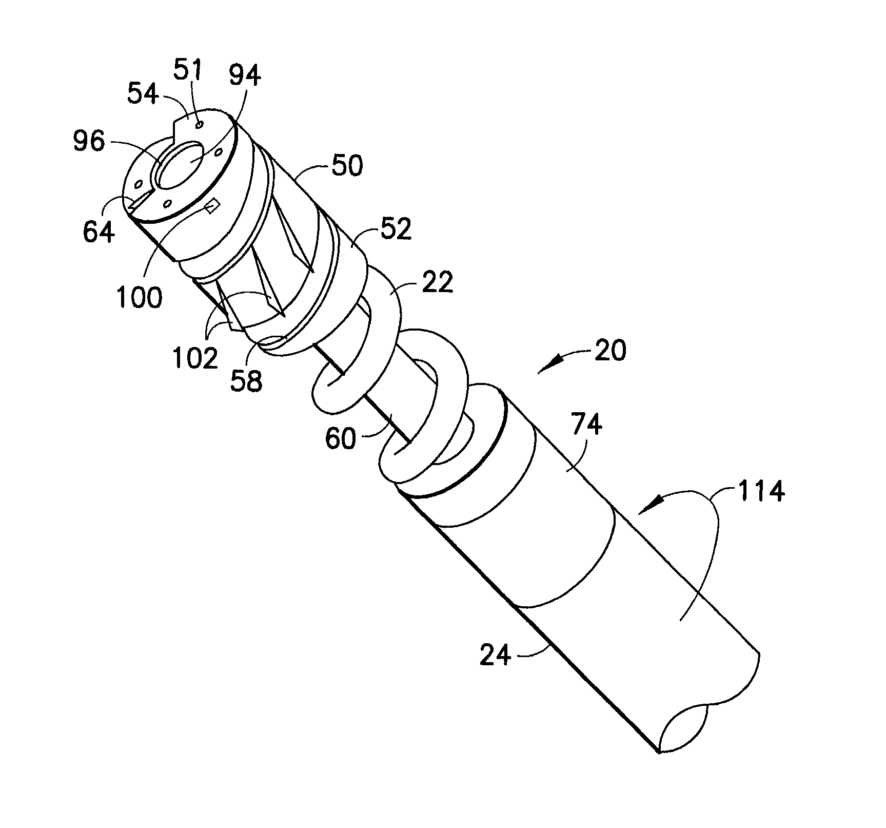
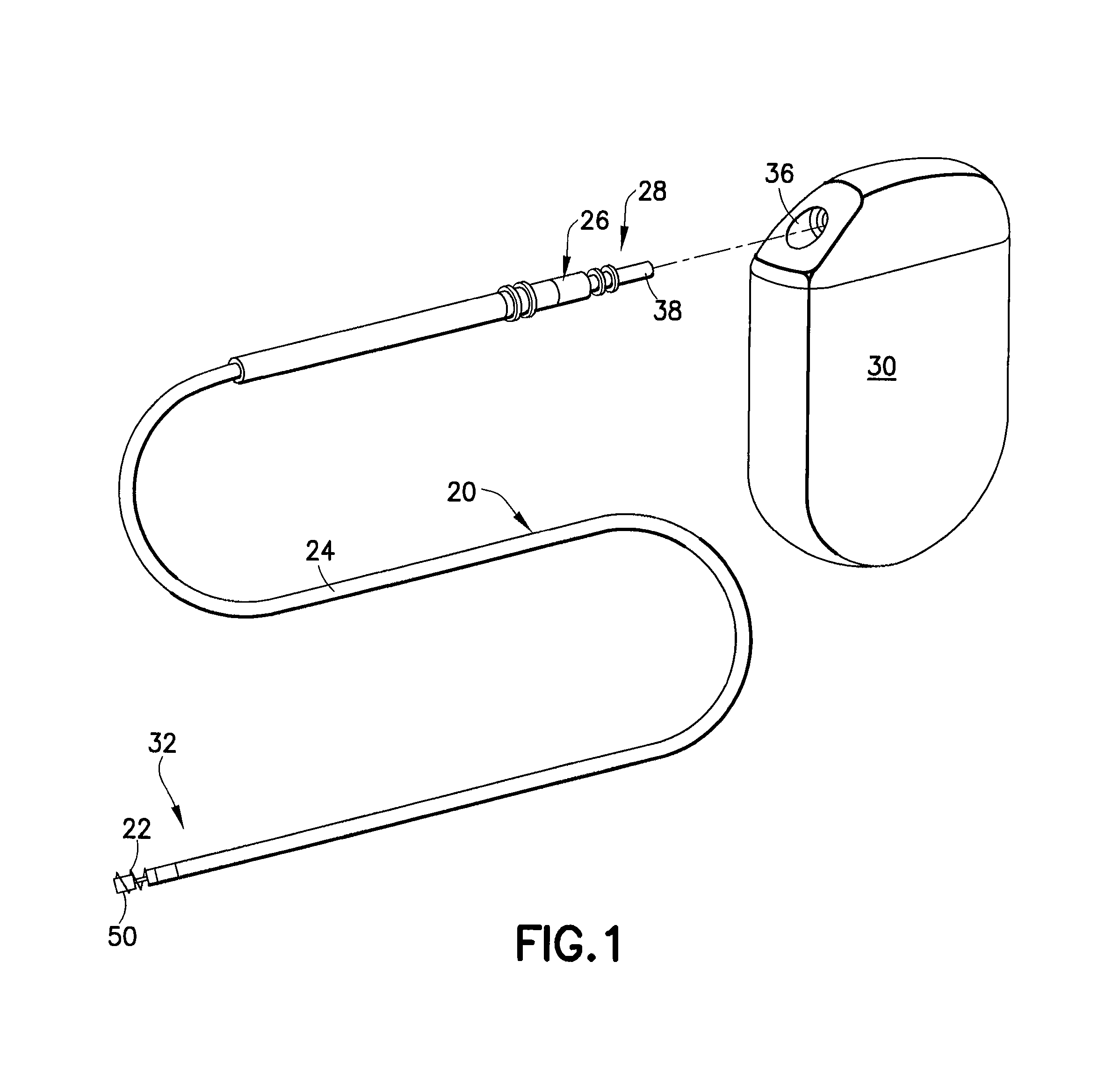
[0050]Referring to FIG. 1, there is shown a diagrammatic perspective view of an endocardial lead 20 incorporating features of the present invention. Although the present invention will be described with reference to the embodiments shown in the drawings, it should be understood that the present invention can be embodied in many alternate forms or embodiments. In addition, any suitable size, shape or type of elements or materials could be used. The lead 20 is attached to body tissue such as an interior wall of a heart by means of a fixation helix 22 at the distal end 32 for firmly engaging the tissue of the heart. Historically, the most successful fixation mechanism for pacing and ICD leads has been in the form of a screw-in fixation helix that can also serve as a helix electrode. This allows for the active fixation of a pacemaker lead in the myocardium, as well as for the acute removal if pacing and sensing parameters are not optimal.

[0051]Lead 20 further comprises a protector membe...


PUM


Abstract

An implantable active fixation lead includes an outer sheath, a protector member having a peripheral surface extending between its distal and proximal end surfaces with a helical groove formed in the peripheral surface, and a fixation helix integral with the outer sheath. The fixation helix includes a tip end engageable with body tissue and slidably engaged with the helical groove for relative translation and rotation. A longitudinal force on the lead firmly engages the protector member's distal end surface with the body tissue. With the fixation helix initially retracted proximally of the protector member's distal end surface and disengaged from the body tissue, upon application of torque to the outer sheath, the distal end surface of the protector member is moved proximally with respect to the fixation helix which, simultaneously, is extended distally beyond the distal end surface of the protector member to an extended position into engagement with the body tissue.

Description

FIELD OF THE INVENTION[0001]The present invention relates generally to implantable leads for medical devices that provide stimulating current to selected body tissue, for example, the heart, and more particularly, to an implantable stimulation lead having a bipolar active fixation electrode for pacing and sensing electrical activity in the heart. Still more particularly, the present invention relates to simplified lead constructions at the distal end that result in more efficient lead delivery with a lead of minimized diameter.BACKGROUND OF THE INVENTION[0002]Implantable cardiac stimulation and sensing devices are well known in the art. Such stimulation devices may include, for example, pacemakers or defibrillators. These devices are generally implanted in an upper portion of the chest beneath the skin of a patient within a surgically-created subcutaneous pocket.[0003]Screw-in leads are notoriously costly and complex and have a lot of variation in performance. These characteristics ...

Claims


Application Information

Patent Timeline
Patent Type & Authority Patents(United States)
IPC IPC(8): A61N1/05
CPCA61N1/0573
Inventor BUSH, MARY ELIZABETHHILL, ROLFCONGER, STEVEN R.STEGFELDT, OLOF
Owner PACESETTER INC
Why Eureka
Try Eureka