Continuously variable valve lift device

A variable valve lift technology, applied in the direction of valve devices, machines/engines, mechanical equipment, etc., can solve the problems of large space occupation and low reliability, and achieve small space occupation, high reliability, and compact device structure Effect

Active Publication Date: 2015-08-05
HANGZHOU BRANCH ZHEJIANG GEELY AUTOMOBILE RES INST +2
View PDF7 Cites 0 Cited by
  • Summary
  • Abstract
  • Description
  • Claims
  • Application Information

AI Technical Summary

Problems solved by technology

[0005] The purpose of the present invention is to provide a simple and reliable continuously variable valve lift device to solve the problems of low reliability and large space occupation in the background technology

Method used


Image

  • Continuously variable valve lift device
  • Continuously variable valve lift device

Examples


Embodiment

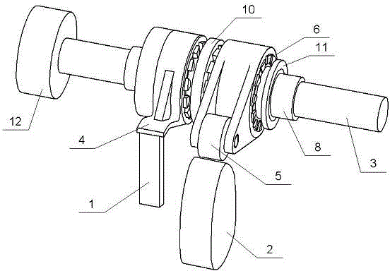
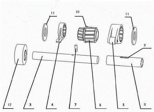
[0019] A continuously variable valve lift device, such as figure 1 and figure 2 As shown, it includes a valve assembly 1, a cam 2 and an axially movable control shaft 3. The control shaft 3 is covered with two helical gears linked with it. The teeth of the two helical gears are inclined in opposite directions. One helical gear is provided with The swing rocker arm 4 adapted to it is provided with a roller rocker arm 5 adapted to it on the other helical gear, and the opposite end faces of the two helical gears are connected to form an integrated combined gear 6. The combined gear 6 and the radial direction of the control shaft 3 are provided with pin holes, the combination gear 6 and the control shaft 3 are connected through the fixed pin 7 inserted into the pin hole, a conduit 8 is set between the control shaft 3 and the combination gear 6, and the conduit 8 Fixedly installed, the guide tube 8 is provided with a bar-shaped hole 9, the length direction of the bar-shaped hole ...


PUM


Abstract

The invention relates to a continuous variable valve lift device and aims to provide the continuous variable valve lift device with a simple and reliable structure. The continuous variable valve lift device comprises a valve component, a cam and a control shaft capable of moving axially, wherein the control shaft is sleeved with two helical gears linked with the control shaft; the two helical gears have opposite tooth inclining directions; one helical gear is provided with a swinging rocker arm matched with the helical gear; the other helical gear is provided with a roller rocker arm matched with the helical gear; the roller rocker arm is propped against the edge of the cam to generate interaction; and the swinging rocker arm is propped against the valve component to generate interaction. The continuous variable valve lift device has the benefits that the continuous variable valve lift is realized; and the device has compact structure, small occupied area and high reliability, and is suitable for popularization and use.

Description

technical field [0001] The invention relates to an automobile engine valve lift device, in particular to a continuously variable valve lift device. Background technique [0002] The opening and closing time and lift of the intake and exhaust valves of traditional engines are fixed, so that the engine can only be in the best gas distribution state under a certain working condition, and the engine speed is very low or very high. , its air distribution will be in an unsatisfactory state. For example, when the engine rotates at low speed, because the valve overlap angle and lift are larger than the ideal value, the flow inertia of the gas is small, and the excessive valve lift is not conducive to the formation of intake vortex, which makes the fuel and air mix unevenly. Part of the fresh air is taken away by the exhaust gas, which is not conducive to combustion; at high speeds, because the valve lift is smaller than the ideal value, the intake air volume is insufficient, which ...

Claims


Application Information

Patent Timeline
Patent Type & Authority Patents(China)
IPC IPC(8): F01L13/00
Inventor 高川由毅沈源刘岩康世邦赵福全
Owner HANGZHOU BRANCH ZHEJIANG GEELY AUTOMOBILE RES INST
Why Eureka
Try Eureka