Circuit breaker interlocking device

A circuit breaker and interlocking technology, applied in circuits, electrical components, electrical switches, etc., can solve the problems of rated current limitation, large floor space, and inability to protect transformers, and achieve the effect of stable support

Inactive Publication Date: 2013-07-03
BEIJING JOYO ELECTRIC CO LTD
View PDF4 Cites 1 Cited by
  • Summary
  • Abstract
  • Description
  • Claims
  • Application Information

AI Technical Summary

Problems solved by technology

The load switch cannot break the fault current. Although the load switch fuse combination can break the short-circuit fault and ground fault, its rated current is limited by the capacity of the fuse, and the rated current can only be 125A.
This means that transformers with a capacity above 1250KVA will not be able to protect
The traditional fixed circuit breaker cabinet is bulky and occupies a large area, which is not suitable for use in pre-installed switchgear such as box-type substations and box-type switching stations.
Although there are circuit breaker solutions derived from the XGN15-12 cabinet type on the market, the interlock mechanism and the circuit breaker need to be specially made, and the research and development costs and production costs are high
The current circuit breaker interlocking mechanism has a complex structure and is not easy to produce, process and assemble

Method used


Image

  • Circuit breaker interlocking device

Examples


Embodiment Construction

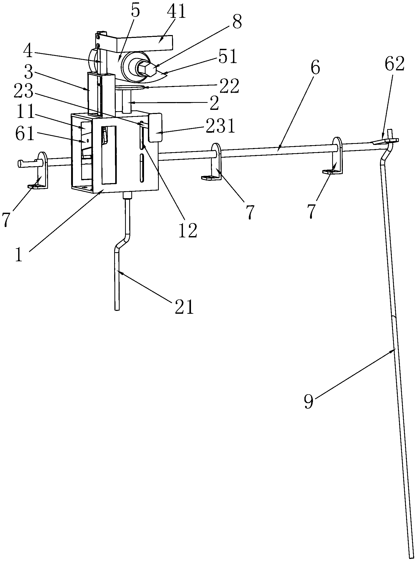
[0015] Such as figure 1 As shown, the first embodiment of the circuit breaker interlocking device of the present invention includes a support seat 1 in a rectangular frame, on which a pressure rod 2 is slidably connected in the up and down direction, and the upper end of the pressure rod 2 and the lower end of the pressure rod 2 both pass through Out of the support seat 1, the lower end of the pressure rod 2 is connected with the circuit breaker closing locking link 21, and the upper end of the pressure rod 2 is fixed with the top end plate 22 of the pressure rod, and the plane where the top end plate 22 of the pressure rod is located is perpendicular to the axis of the pressure rod 2 , the upper end surface of the support seat 1 is fixed with a support frame 3 in a rectangular frame, the support frame 3 is located on the left side of the top plate 22 of the pressure bar, and the support frame 3 is slidably connected with a square connecting rod 4 along the up and down directio...


PUM


Abstract

The invention discloses a circuit breaker interlocking device, relates to an interlocking device of an electric switch, in particular relates to interlocking between a circuit breaker and an isolating switch, and aims to provide the circuit breaker interlocking device, which is simple in structure, and easy to process and assemble. The circuit breaker interlocking device comprises a supporting seat (1), a pressing rod (2), an interlocked circuit breaker switch-on locking connecting rod (21), a pressing rod top plate (22), a supporting frame (3), a square connecting rod (4), a baffle (41), an isolating switch operating shaft sleeve (5), a flange plate (51) and a connecting rod (6), wherein the connecting rod is rotatably inserted into at least two supporting bending plates (7); a first crank arm plate (61) is fixedly arranged on the connecting rod; a first crank arm plate movable groove (11) is formed in the rear end surface of the supporting seat; an elongated circular hole is formed in the first crank arm plate; the lower end of the square connecting rod is connected to the elongated circular hole through a pin shaft; a second crank arm plate (62) is fixedly arranged at the right end of the connecting rod; and an interlocked circuit breaker spindle crank arm connecting rod (9) is connected to the second crank arm plate.

Description

technical field [0001] The invention relates to an interlocking device for an electric switch, in particular to an interlocking device for a circuit breaker and a disconnector. Background technique [0002] XGN15-12 unit type SF6 ring network cabinet is suitable for AC 50HZ, 12KV power system, widely used in industrial and civil cable ring network and power supply terminal, especially suitable for the following places: power distribution in urban residential areas, small secondary substations, Switchgear, industrial and mining enterprises, shopping malls, airports, subways, wind power, hospitals, stadiums, railways, tunnels, etc. [0003] At present, the main power supply scheme of the traditional XGN15-12 ring network cabinet is SF6 load switch or SF6 load switch fuse combination appliance. The load switch cannot break the fault current. Although the load switch fuse combination can break the short-circuit fault and ground fault, its rated current is limited by the capacit...

Claims


Application Information

Patent Timeline
Patent Type & Authority Applications(China)
IPC IPC(8): H01H9/26
Inventor 李宗义李旭晗郝俊红
Owner BEIJING JOYO ELECTRIC CO LTD
Why Eureka
Try Eureka