
Installation system used for power source distribution device

A technology for installation system and power distribution, which is applied in the direction of coupling devices, circuits, electrical components, etc., and can solve problems such as falling off and power distribution units sliding

Inactive Publication Date: 2013-07-03
EATON MFG LP GLASGOW SUCCURSALE DE MOR
View PDF5 Cites 5 Cited by
  • Summary
  • Abstract
  • Description
  • Claims
  • Application Information

AI Technical Summary

Problems solved by technology

The disadvantage of this installation system is that when the power distribution unit product is heavy or encounters a large vertical external force, the power distribution unit will slide or even fall off relative to the sliding frame

Method used


Image

  • Installation system used for power source distribution device
  • Installation system used for power source distribution device
  • Installation system used for power source distribution device

Examples


Embodiment Construction

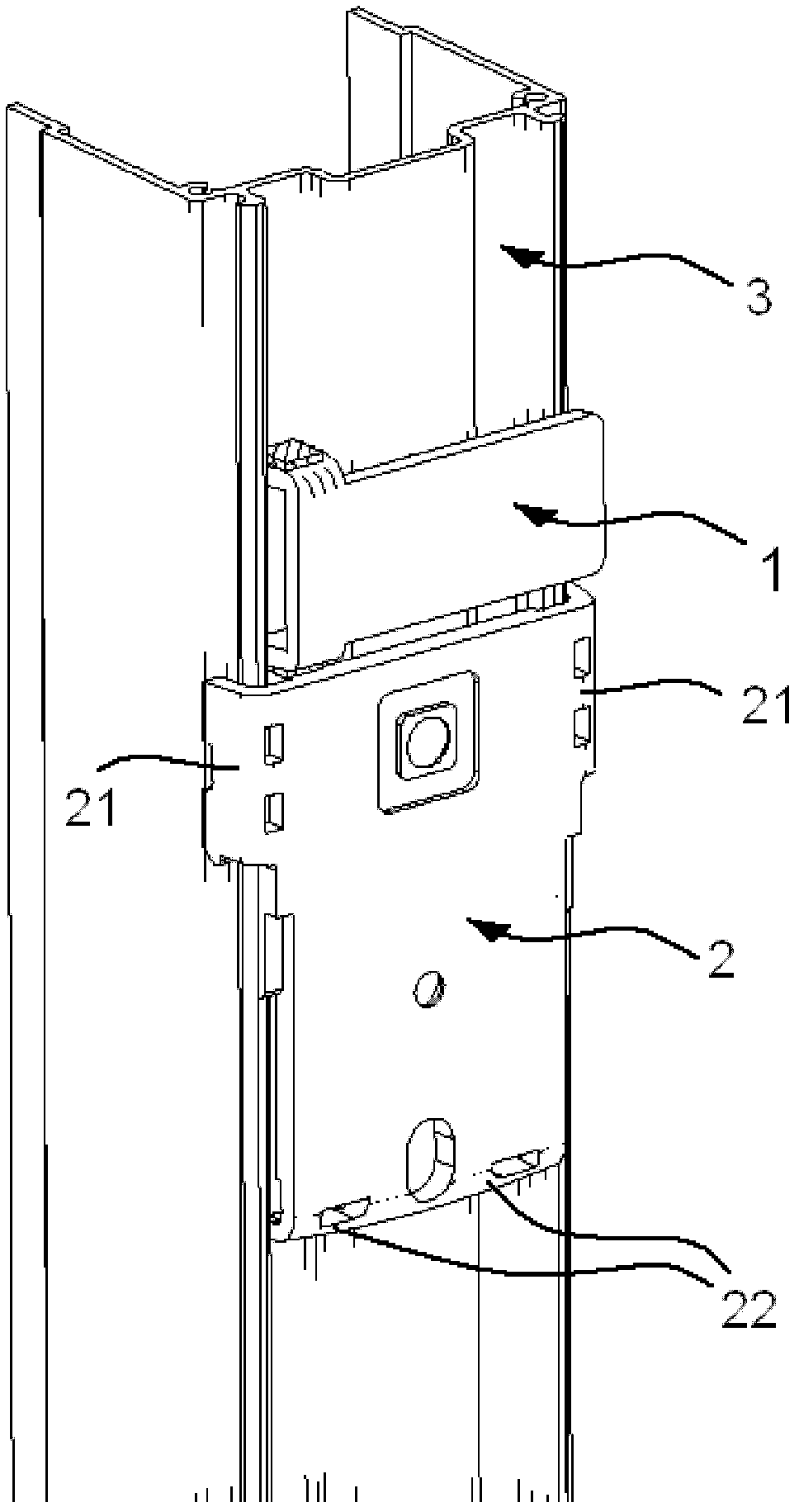
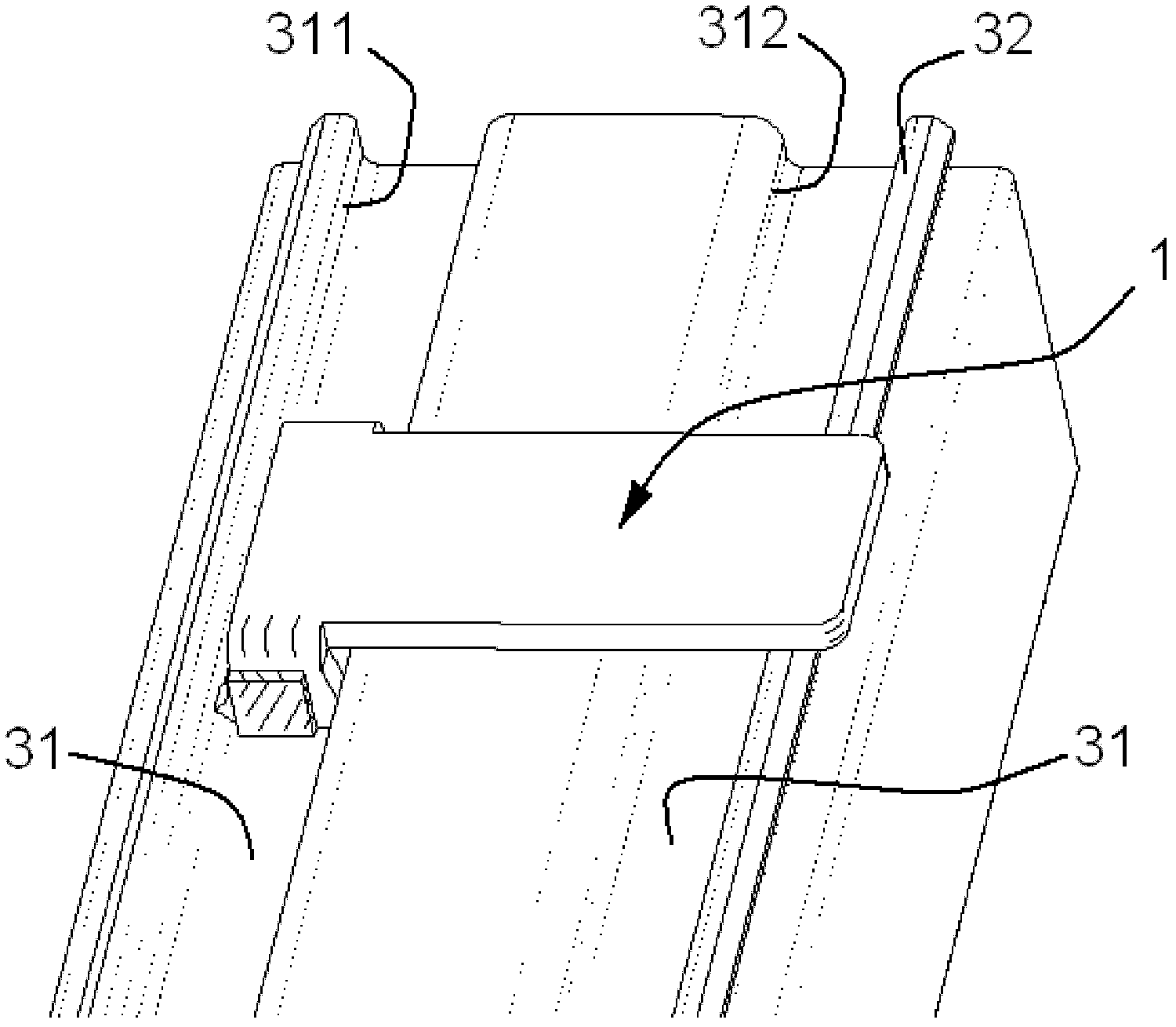
[0021] figure 1 A mounting system for a power distribution device is schematically shown, and the mounting system includes a sliding frame 2 , a sliding rail 3 press-fitted into the sliding frame 2 , and a positioning member 1 mounted on the sliding rail 3 .

[0022] The sliding frame 2 is roughly in the shape of a plate, and the upper end and the lower end thereof are respectively provided with perforations for fixing connectors such as bolts to pass through to fix the sliding frame 2 on the frame or other fixtures. In addition to being fixed to the frame through the connecting device as a separate piece, the sliding frame 2 can also be integrally formed with the frame.

[0023] The slide rail 3 is in the shape of a long straight strip, which is the bottom cover of the power distribution device. Of course, the slide rail 3 can also be a component independent from the bottom cover of the power distribution device and be fixed to the bottom cover by appropriate means. The bot...


PUM


Abstract

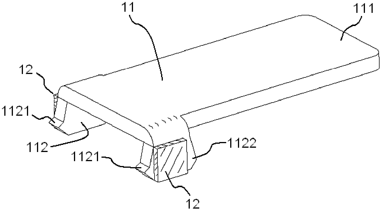
The invention relates to an installation system used for a power source distribution device. The installation system comprises a fixed sliding frame and a sliding rail which is installed in the sliding frame in a pressed mode, wherein the sliding rail is provided with a power source distribution device and at least one groove which is formed along the longitudinal direction of the sliding rail, the groove is provided with a first side face and a second side face which are opposite, and a positioning part which prevents the sliding frame and the sliding rail from relatively sliding is installed on at least one groove. The positioning part is composed of a body which horizontally extends along the sliding rail, the body is provided with a side face which abuts against the sliding frame and two ends opposite to the horizontal direction, one end is provided with a release portion, the release portion is in squeezing fit with a first side face and a second side face of the groove, one end, opposite to the release portion, of the body is a free end, and the release portion is provided with a protrusion portion to be used as a balance pivot, and the release portion is pressed into the groove or pulled out of the groove by the free end.

Description

technical field [0001] The invention relates to a power distribution device, in particular to a sliding rail-slider type power distribution device installation system. Background technique [0002] Existing information centers are mostly composed of many racks, and each rack has multiple horizontally placed servers or uninterruptible power supply systems from top to bottom. In order to distribute power to the servers and the UPS in the rack, usually a power distribution unit that provides multiple sockets like a household power strip is assembled vertically or horizontally in the rack. However, since there is no uniform regulation in the industry on the vertical spacing of the assembly holes on the rack, the researchers designed a slide rail-sled type power distribution unit installation system for this purpose. Patent document US2002022406A1 discloses a typical slide rail-sled type power distribution unit installation system, the installation system includes a track struct...

Claims


Application Information

Patent Timeline
IPC IPC(8): H01R31/02H01R13/46
Inventor 陈家智
Owner EATON MFG LP GLASGOW SUCCURSALE DE MOR
Learn More