Low-frictional-characteristic air cylinder with piezoelectrically actuated cylinder barrel deviously vibrating

A flexural vibration, low friction technology for applications such as fluid pressure actuation devices

Inactive Publication Date: 2013-07-10
HARBIN INST OF TECH
View PDF6 Cites 11 Cited by
  • Summary
  • Abstract
  • Description
  • Claims
  • Application Information

AI Technical Summary

Problems solved by technology

However, this system tends to increase in volume and is easy to introduce oil pollution

Method used


Image

  • Low-frictional-characteristic air cylinder with piezoelectrically actuated cylinder barrel deviously vibrating
  • Low-frictional-characteristic air cylinder with piezoelectrically actuated cylinder barrel deviously vibrating

Examples


specific Embodiment approach 1

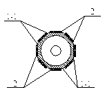
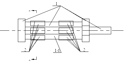
[0011] Specific implementation one: See Figure 1, figure 2 For illustration, this specific embodiment is composed of a cylinder assembly 1 and a plurality of piezoelectric expansion sheets 2;

[0012] On the outer circular surface of the cylinder barrel of the cylinder assembly 1, a plurality of planes 1-1 opposite to each other are arranged around the circumferential direction. The total number of planes 1-1 is a multiple of 4, and each plane 1-1 is on One or more piezoelectric stretchable sheets 2 are provided, and the number of piezoelectric stretchable sheets 2 on each plane 1-1 is equal, and one plane of each piezoelectric stretchable sheet 2 is aligned with the plane 1-1. 1 connection, when each plane 1-1 is provided with a plurality of piezoelectric stretch pieces 2, all piezoelectric stretch pieces 2 on this plane are arranged along the axis direction of the cylinder of the cylinder assembly 1; The expansion and contraction direction of the expansion sheet 2 is par...

specific Embodiment approach 2

[0017] Specific implementation two: See Figure 1, figure 2 For illustration, the difference between this specific embodiment and the specific embodiment 1 is that when a plurality of piezoelectric stretchable sheets 2 are arranged on each plane 1-1, all piezoelectric stretchable sheets 2 on this plane are along the cylinder. The axial directions of the cylinders of the assembly 1 are evenly arranged. Other components and connection relationships are the same as in the first embodiment.

[0018] Working principle: It drives the piezoelectric expansion sheet 2 to make the cylinder of the cylinder assembly 1 in a high-frequency bending vibration state, and uses the anti-friction effect generated by the high-frequency bending vibration of the cylinder to reduce the friction between the piston and the cylinder. coefficient, so that the cylinder has low friction characteristics.

[0019] Apply sinusoidal alternating current with the same or similar natural bending vibration fre...


PUM


Abstract

The invention discloses a low-frictional-characteristic air cylinder with a piezoelectrically actuated cylinder barrel deviously vibrating, and belongs to the technical field of pneumatics, particularly the technical field for lowering a frictional coefficient of an air cylinder. In order to realize reduction of the frictional coefficient of the air cylinder conveniently, quickly and flexibly, a plurality of planes which are opposite pairwise are arranged around the periphery of an outer circular face of a cylinder barrel of an air cylinder assembly, one or more piezoelectric extension pieces are arranged on each of the planes, one plane of each piezoelectric extension piece is enabled to be connected with the plane, when a plurality of piezoelectric extension pieces are arranged on each of the planes, all the piezoelectric extension pieces arranged on the plane are arranged along the axial direction of the cylinder barrel of the air cylinder assembly, extension direction of the piezoelectric extension pieces is parallel to an axis of the cylinder barrel of the air cylinder assembly, and frequency of driving voltage of the piezoelectric extension pieces is identical or close to intrinsic bending vibration frequency of the cylinder barrel. By the low-frictional-characteristic air cylinder with the piezoelectrically actuated cylinder barrel deviously vibrating, when the piezoelectric extension pieces input a driving signal, the frictional coefficient of a piston and the cylinder barrel can be lowered.

Description

technical field [0001] The invention belongs to the technical field of pneumatics, in particular to the technical field of reducing the friction coefficient of a cylinder. Background technique [0002] The phenomenon of cylinder crawling seriously affects the smoothness of cylinder movement. In order to effectively eliminate the crawling phenomenon and improve the low-speed operation characteristics of the cylinder, a well-known method is to compensate the friction force of the cylinder by superimposing the chatter signal on the control signal, eliminating the directionality of the cylinder friction force, thereby reducing the cylinder crawling phenomenon . However, it is difficult to properly grasp the frequency and amplitude of the flutter signal in practical applications, which often brings side effects such as noise and jitter. [0003] Another method is to introduce a layer of air film between the cylinder friction pairs by using the air floating effect. The piston a...

Claims


Application Information

Patent Timeline
Patent Type & Authority Applications(China)
IPC IPC(8): F15B15/20
Inventor 包钢程廷海肖承丰高焓陈兴隆王维
Owner HARBIN INST OF TECH
Why Eureka
Try Eureka