Wafer prealignment device

A pre-alignment and wafer technology, applied in electrical components, semiconductor/solid-state device manufacturing, circuits, etc., can solve problems such as tilt, uneven force, and inability to clamp wafers

Active Publication Date: 2013-07-10
SHENYANG SIASUN ROBOT & AUTOMATION
View PDF3 Cites 2 Cited by
  • Summary
  • Abstract
  • Description
  • Claims
  • Application Information

AI Technical Summary

Problems solved by technology

At present, the most widely used wafer pre-alignment device is the three-claw pre-alignment machine. For the clamping of the wafer, most of the clamping methods are carried out by moving one of the claws radially. The problem with this method is that, In the process of pre-alignment, the wafer is first placed on the support, and then the jaws rise to receive the wafer and exceed the support, and then clamp the wafer. If the three-claw type is used and one of the claws is movable, and The other two claws are not movable, that is to say, the other two claws always maintain a state no matter whether they clamp or loosen the wafer. In this way, when the claws rise or fall, it is entirely possible to cause the wafer to be unbalanced and tilted, resulting in inability to Consequences of wafer clamping
In addition, some use two claws or four claws to clamp the edge of the wafer symmetrically and move relative to each other, so that the edge of the wafer is only subjected to forces from two opposite directions, and the uneven force may also cause the wafer to be unable to be clamped. s consequence

Method used


Image

  • Wafer prealignment device
  • Wafer prealignment device
  • Wafer prealignment device

Examples


Embodiment Construction

[0028] The above-mentioned wafer pre-alignment device will be further described below through specific embodiments and accompanying drawings.

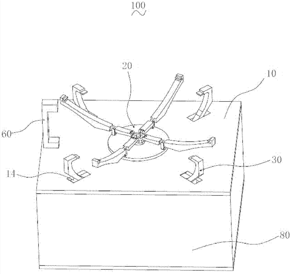
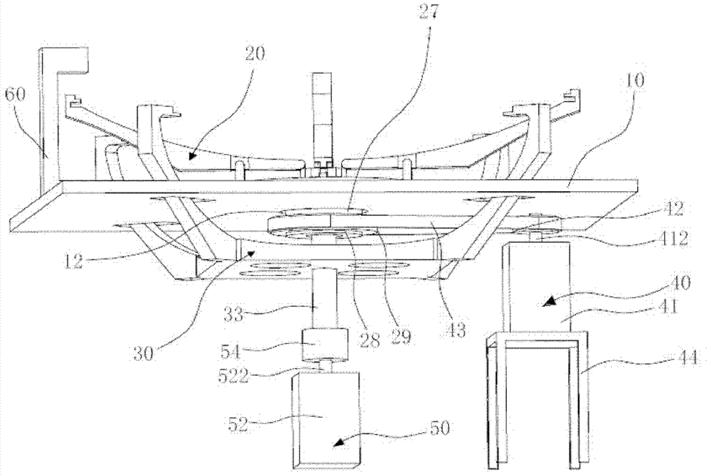
[0029] Please also see figure 1 , figure 2 and Figure 5 , a wafer pre-alignment device 100 according to one embodiment includes a substrate 10, a first supporting device 20, a second supporting device 30, a first driving device 40, a second driving device 50, a sensor 60, and a control unit (not shown in the figure) ), bearing 70 and protection box 80.

[0030] The substrate 10 is substantially a rectangular plate, and a first through hole 12 and a plurality of second through holes 14 are opened on the substrate 10 . The first through hole 12 is opened in the middle of the substrate 10 , and the second through hole 14 is located around the first through hole 12 . In this embodiment, the number of the second through holes 14 is four.

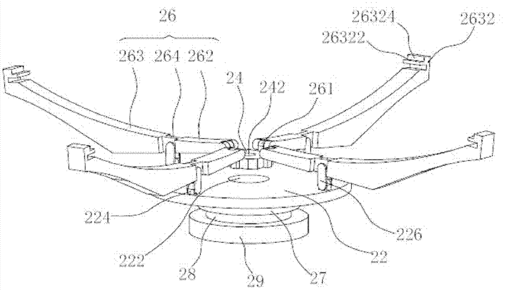
[0031] see image 3 , the first support device 20 includes a support base 22 , a connector 24 ...


PUM


Abstract

A wafer prealignment device comprises a base plate, a first support device, a first drive device, a second support device and a second drive device, wherein the first support device is arranged on the base plate, the first drive device is used for driving the first support device to rotate relative to the base plate, part of the second support device is arranged on the lower portion the base plate, and the second drive device is used for driving the second support device to move vertically relative to the base plate. The first support device comprises a plurality of first support arms used for supporting a wafer. The second support device comprises a plurality of second support arms used for supporting the wafer. In the process of prealignment, the handover of the wafer can be achieved through the rotation of the first support device and the vertical movement of the second support device, and the position adjustment of the wafer is achieved in the process of handover. In the process of the rotation of the first support device and the vertical movement of the second support device, the plurality of first support arms or the plurality of second support arms move at the same time, the wafer is enabled to be stressed evenly, the consequence that the wafer cannot be supported can not occur, and wafer stable handover is achieved so as to finish the prealignment. The wafer prealignment device is good in stability and capable of greatly improving the prealignment efficiency.

Description

technical field [0001] The invention relates to the field of integrated circuit manufacturing, in particular to a wafer pre-alignment device. Background technique [0002] Wafer pre-alignment control is an important link in the integrated circuit manufacturing process. Therefore, the wafer pre-alignment device is an indispensable device in the integrated circuit manufacturing process. The purpose of wafer pre-alignment is to position the wafer before the wafer is transferred to the exposure station, so that the center of the wafer is within a certain range or the wafer notch stays at a suitable angle. At present, the most widely used wafer pre-alignment device is the three-claw pre-alignment machine. For the clamping of the wafer, most of the clamping methods are carried out by moving one of the claws radially. The problem with this method is that, In the process of pre-alignment, the wafer is first placed on the support, and then the jaws rise to receive the wafer and exc...

Claims


Application Information

Patent Timeline
Patent Type & Authority Applications(China)
IPC IPC(8): H01L21/687H01L21/68
Inventor 边弘晔张鹏陈守良曲道奎徐方李学威温燕修邹风山
Owner SHENYANG SIASUN ROBOT & AUTOMATION
Why Eureka
Try Eureka