Optimal secondary regulator of dynamic reactive power compensation device and design method thereof

A secondary regulator and compensation device technology, applied in reactive power compensation, reactive power adjustment/elimination/compensation, etc., can solve complex problems such as control system PID parameter setting, and achieve optimal control performance and excellent system performance Effect

Inactive Publication Date: 2013-07-10
WISDRI ENG & RES INC LTD
View PDF3 Cites 6 Cited by
  • Summary
  • Abstract
  • Description
  • Claims
  • Application Information

AI Technical Summary

Problems solved by technology

[0002] In industrial power systems such as iron and steel, metallurgy, etc., due to load changes, dynamic reactive power compensation needs to be performed on...

Method used


Image

  • Optimal secondary regulator of dynamic reactive power compensation device and design method thereof
  • Optimal secondary regulator of dynamic reactive power compensation device and design method thereof
  • Optimal secondary regulator of dynamic reactive power compensation device and design method thereof

Examples


Embodiment Construction

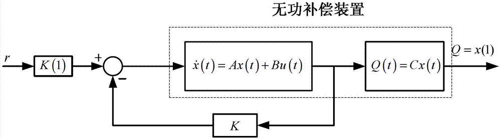
[0023] figure 1 It is a schematic diagram of an embodiment of the present invention, and the optimal secondary regulator of the dynamic reactive power compensation device includes: a reactive power compensation device model, which is used to sample the reactive power Q output by the reactive power compensation device and the thyristor amplification factor u. The order n of the power compensation device model is to use the model identification algorithm to obtain the transfer function of the reactive power compensation device; the continuous time model of the reactive power compensation device is used to design according to the transfer function of the reactive power compensation device in the form of a standard form that can be observed according to the control system theory The continuous time state equation coefficient matrix A, B, C of the reactive power compensation device, then the continuous time state equation of the reactive power compensation device is expressed as Q...


PUM


Abstract

The invention provides a design method of an optimal secondary regulator of a dynamic reactive power compensation device. The design method of the optimal secondary regulator of the dynamic reactive power compensation device comprises the following steps: sampling a reactive power output by the reactive power compensation device and a thyristor amplification coefficient, and obtaining a transfer function of the reactive power compensation device by utilizing a model identification algorithm; in the form of observable standard form of a control system theory, designing a continuous time state equation of the reactive power compensation device; setting up an optimizing index function; solving a Riccati equation; calculating a gain matrix of the optimal secondary regulator of the reactive power compensation device; and obtaining an input thyristor amplification coefficient of a control system of the reactive power compensation device. According to the dynamic and static performance required by a designer, the design method of the optimal secondary regulator of the dynamic reactive power compensation device can obtain the optimal parameters of a controller by solving the Riccati equation, guarantees the system to have the optimal control performance, achieves the tracing control of an output reactive power by utilizing the function of the optimal secondary regulator, and has quite excellent system performance.

Description

technical field [0001] The invention relates to a design method of a dynamic reactive power compensation device control system in an electric power supply system, in particular to an optimal secondary regulator of a dynamic reactive power compensation device and a design method thereof. technical background [0002] In industrial power systems such as iron and steel, metallurgy, etc., due to load changes, dynamic reactive power compensation needs to be performed on the system. At present, the commonly used control method is to use the PID control algorithm to perform closed-loop control on the system. The tuning aspect is more complicated. Reactive power compensation devices used in engineering practice usually adopt several forms of control strategies such as power factor control, voltage control, and reactive power control. These control strategies have one thing in common, which is to adjust the output of reactive power compensation devices by adjusting the thyristor cont...

Claims


Application Information

Patent Timeline
IPC IPC(8): H02J3/18
CPCY02E40/30
Inventor 张华军谢德华
Owner WISDRI ENG & RES INC LTD
Why Eureka
Try Eureka