
Frequency shift repeater based on frequency difference digital compensation and frequency difference digital compensation method

A digital compensation and repeater technology, which is applied in the field of frequency shift repeater and frequency difference digital compensation based on frequency difference digital compensation, and can solve problems such as frequency difference

Inactive Publication Date: 2013-07-10
深圳格兰泰克科技有限公司
View PDF3 Cites 3 Cited by
  • Summary
  • Abstract
  • Description
  • Claims
  • Application Information

AI Technical Summary

Problems solved by technology

[0006] The present invention provides a frequency shift repeater based on frequency difference digital compensation and a frequency difference digital compensation method to solve the problem of frequency difference between the near end and the far end in the prior art

Method used


Image

  • Frequency shift repeater based on frequency difference digital compensation and frequency difference digital compensation method

Examples


Embodiment 1

[0042] When compensating the downlink IF input signal, set the frequency of the downlink IF input signal as NFD_FREQ0, and its frequency conversion compensation frequency DIF_DN_IN_FREQ is:

[0043] DIF_DN_IN_FREQ=NFD_FREQ0*FDF=-NFD_FREQ0 / REF_FREQ0*DIF_REF

[0044] Formula (6)

[0045] The 32-bit frequency word corresponding to the frequency conversion compensation frequency is:

[0046]DIF_DN_IN_FREQ_FW=-NFD_FREQ0 / REF_FREQ0*DIF_REF_FW formula (7)

Embodiment 2

[0048] When compensating the uplink intermediate frequency output signal, set the frequency of the uplink intermediate frequency output signal as NFU_FREQ0, and its frequency conversion compensation frequency DIF_UP_OUT_FREQ is:

[0049] DIF_UP_OUT_FREQ=NFU_FREQ0*(-FDF)=NFU_FREQ0 / REF_FREQ0*DIF_REF

[0050] Formula (8)

[0051] The 32-bit frequency word corresponding to the frequency conversion compensation frequency is:

[0052] DIF_UP_OUT_FREQ_FW=NFU_FREQ0 / REF_FREQ0*DIF_REF_FW formula (9)

[0053] Preferably, the remote machine also includes a voltage-controlled crystal oscillator, and the remote frequency compensation circuit includes a radio frequency compensation circuit, which receives the frequency difference coefficient from the frequency difference coefficient generation circuit, and is used for adjusting the uplink radio frequency input signal and the frequency difference coefficient of the remote machine accordin...

Embodiment 3

[0055] When compensating the downlink RF output signal, set the frequency of the downlink RF output signal as FD_FREQ0, and its frequency conversion compensation frequency DIF_FD_OUT_FREQ is:

[0056] DIF_FD_OUT_FREQ=FD_FREQ0*(-FDF)=FD_FREQ0 / REF_FREQ0*DIF_REF

[0057] Formula (10)

[0058] The corresponding 32-bit frequency word is:

[0059] DIF_FD_OUT_FREQ_FW=FD_FREQ0 / REF_FREQ0*DIF_REF_FW formula (11)


PUM


Abstract

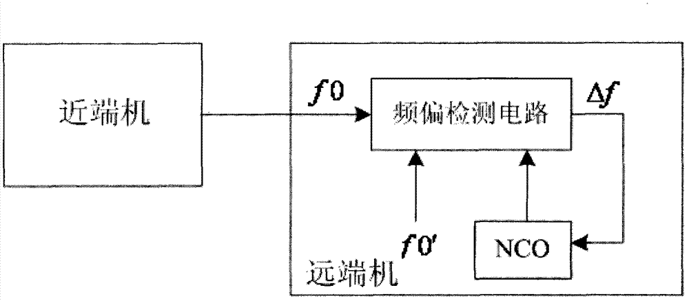
The invention provides a frequency shift repeater based on frequency difference digital compensation and a frequency difference digital compensation method. The frequency shift repeater comprises a near-end machine and a far-end machine, wherein the near-end machine inserts a reference signal of a single frequency into a relay frequency band of a downlink signal, the far-end machine is connected with the near-end machine in a communication mode, the far-end machine comprises a frequency deviation detecting circuit and a far-end frequency compensation circuit, the frequency deviation detecting circuit receives the downlink signal and is used for detecting a frequency difference value between the reference signal in the downlink signal and a local oscillator signal of the far-end machine, and the far-end frequency compensation circuit is used for conducting frequency compensation to an uplink signal and the downlink signal of the far-end machine according to the frequency difference value. The reference signal is inserted into the relay frequency band of the downlink signal by the near-end machine, the far-end machine detects the frequency difference value between the reference signal and the local oscillator signal of the far-end machine and conducts the frequency difference compensation to the uplink signal and the downlink signal according to the frequency difference value, and therefore frequency of the near-end machine and frequency of the far-end machine are synchronous and the frequency difference between the near-end machine and the far-end machine is eliminated.

Description

technical field [0001] The invention relates to the field of frequency-shifting repeaters, in particular to a frequency-shifting repeater based on frequency difference digital compensation and a frequency difference digital compensation method. Background technique [0002] In the frequency-shifting repeater, due to the deviation between the frequencies of the crystal oscillators of the near-end and the far-end, the RF local oscillators of the two have frequency deviations, so that the service signal generates a frequency after passing through the frequency-shifting repeater. shift. Calculated according to the crystal oscillator frequency deviation of + / -2.5ppm, in the 900M frequency band, the frequency deviation is + / -2250Hz. The frequency deviation (ie, frequency difference) will seriously affect the receiving performance of the mobile phone and the base station. [0003] In the prior art, the following methods are usually adopted to solve the problem of large frequency ...

Claims


Application Information

Patent Timeline
Patent Type & Authority Applications(China)
IPC IPC(8): H04B7/155
Inventor 贾学卿
Owner 深圳格兰泰克科技有限公司
Learn More