Synchronous data transmission system

a data transmission and data technology, applied in data switching networks, data multiplexes, instruments, etc., can solve problems such as stoppage of reproduction or data in the reproduction or data transmission field, data transmission quality deterioration, and data transmission is subject to quality degradation. , to achieve the effect of reducing the quality deterioration of data transmission

Inactive Publication Date: 2008-04-15
LENOVO INNOVATIONS LTD HONG KONG
View PDF29 Cites 0 Cited by
  • Summary
  • Abstract
  • Description
  • Claims
  • Application Information

AI Technical Summary

Benefits of technology

[0005]An object of the present invention is therefore to provide a synchronous data transmission system capable of reducing quality deterioration of data transmission due to an overflow or underflow generated by the difference between the transmission side data generation sampling clock and the reception side data reproducing sampling clock.
[0010]The synchronous data transmission system further comprising a sampling clock synchronizing means for synchronizing the sampling clocks of the sampling clock generators in the first and second terminals by inputting the output of the sampling clock generator in one terminal to the sampling clock generator in another terminal. The frequency difference between the sampling clocks generated in the sampling clock generators in the first and second terminals is eliminated by inputting the clock from the sampling clock generator in one terminal to the sampling clock generator in another terminal. The sampling clock frequency of one terminal is made closer to the sampling clock frequency of another terminal by estimating the sampling clock on the basis of the data received from the asynchronous transmission line.

Problems solved by technology

In such cases, the data transmission is subject to quality deterioration due to different data sampling clocks of the individual terminals.
For example, when the transmission side data generation sampling clock is at a higher rate than the reception side data reproduction sampling clock, overflow of data is generated on the reception side, resulting in missing of reproduced data.
On the other hand, when the reception side sampling clock is at a higher rate, underflow of data is generated, resulting in stoppage of the reproduction or missing data therein.

Method used


Image

  • Synchronous data transmission system
  • Synchronous data transmission system
  • Synchronous data transmission system

Examples


Embodiment Construction

[0017]Preferred embodiments of the present invention will now be described with reference to the drawings.

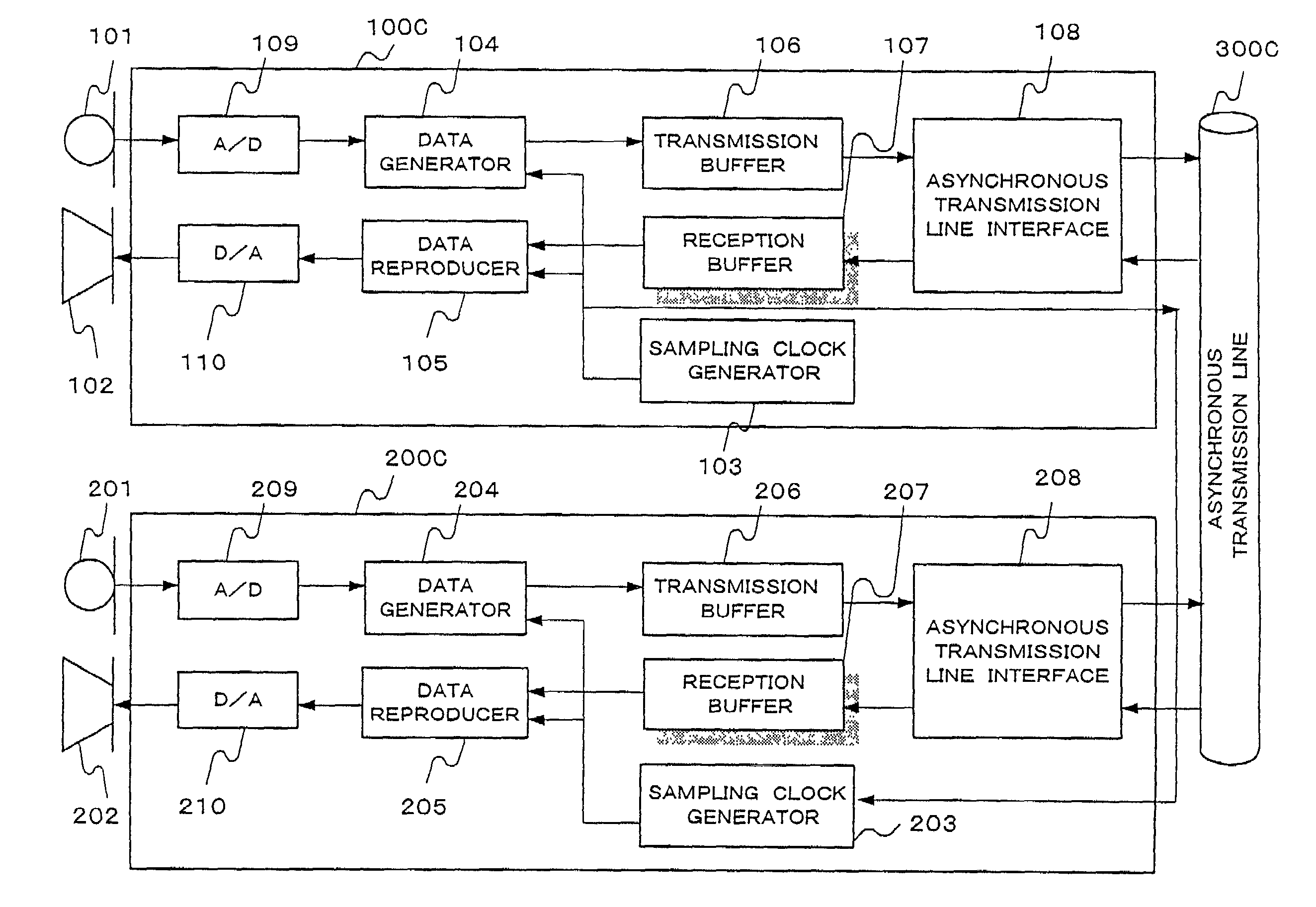
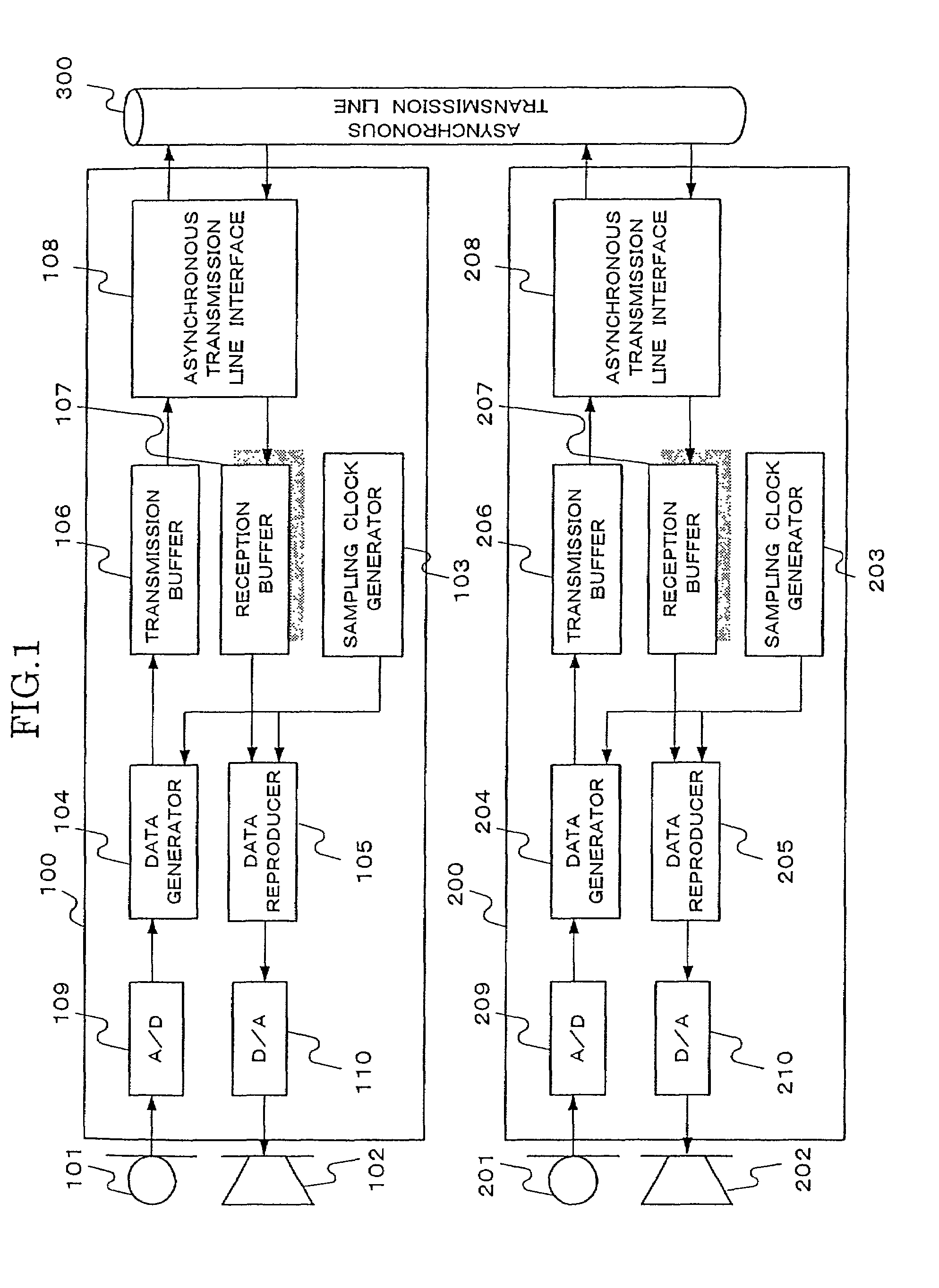
[0018]According to the present invention, in the transmission of a synchronous signal, such as a voice or a motion picture signal, between different terminals (i.e., a first and a second terminal) via an asynchronous transmission line, deterioration of the data quality is presented, which might otherwise be generated due to the difference of a transmission side data generation sampling clock and a reception side data reproduction sampling clock from each other. FIG. 1 is a block diagram showing the construction of a first embodiment of the synchronous data transmission system according to the present invention. This embodiment concerns the transmission of voice as signal transmitted and received between such terminals.

[0019]The synchronous data transmission system shown in FIG. 1 comprises a first and a second terminal 100 and 200 and a synchronous transmission line 300. Microph...


PUM


Abstract

A first and a second terminals 100 and 200 are connected to an asynchronous transmission line 300. Microphones 101 and 201 and loudspeakers 102 and 202, or image input units (i.e., cameras) 111 and 211 and image output units (i.e., displays) 112 and 212, are connected to the first and second terminals 100 and 200, respectively. The terminals 100 and 200 comprise sampling clock generators 103 and 203, data generators 104 and 204, data reproducers 105 and 205, transmission buffers 106 and 206 and n- (or plural) stage reception buffers 107 and 207. Thus, it can prevent data quality deterioration due to an overflow or an underflow when transmitting such data as voice or image data between the first and the second terminals via an asynchronous transmission line.

Description

BACKGROUND OF THE INVENTION[0001]This application claims benefit of Japanese Patent Application No. 2000-236718 filed on Aug. 4, 2000, the contents of which are incorporated by the reference.[0002]The present invention relates to synchronous data transmission systems for transmitting synchronous data via a synchronous line.[0003]There are cases where it is desired to transmit synchronous signal varying with time, such as voice and motion picture signals among a plurality of terminals via a synchronous transmission lines. Prior art techniques concerning such synchronous data transmission are disclosed in Japanese Patent Laid-Open No. 62-125728 as “Clock Permeable Synchronous Data Transmission System”, in Japanese Patent Laid-Open No. 63-187942 as “Data Transmission System” and so forth.[0004]In such cases, the data transmission is subject to quality deterioration due to different data sampling clocks of the individual terminals. For example, when the transmission side data generation...

Claims


Application Information

Patent Timeline
Patent Type & Authority Patents(United States)
IPC IPC(8): H04J3/06H04Q11/04H04L7/00
CPCH04Q11/0478H04L2012/5674
Inventor NAMIKI, HIDEO
Owner LENOVO INNOVATIONS LTD HONG KONG
Why Eureka
Try Eureka