Terminal apparatus and controlling method for optical output power

Inactive Publication Date: 2005-09-22
FUJITSU LTD
View PDF4 Cites 30 Cited by
  • Summary
  • Abstract
  • Description
  • Claims
  • Application Information

AI Technical Summary

Benefits of technology

[0019] According to another aspect of the present invention, there is provided a controlling method for optical output power for being executed by an extension system having a function for controlling, when a plurality of signal lights individually having different wavelengths are to be extended for an existing optical transmission system, a total optical output power of an existing wavelength signal light and extension wavelength signal lights to a fixed level, comprising a relative level adjustment step of adjusting relative levels of the optical output powers of the extension wavelength signal lights based on Q values or OSNRs of signal lights received by a terminal apparatus on the receiving side included in the extension system, and an absolute level adjustment step of increasing the levels of the optical output powers of the extension wavelength signal lights at the same time while the relative level differences of the optical output powers of the extension wavelength signal lights is maintained so that the optical output power of the light signals of the existing optical transmission system may not become lower than a minimum permissible optical output power to adjust the absolute levels of the existing wavelength signal light and the extension wavelength signal lights.
[0020] According to a further aspect of the present invention, there is provided a computer-readable storage medium which stores an optical output power controlling program for causing, when a plurality of signal lights individually having different wavelengths are to be extended for an existing optical transmission system, a computer provided for an extension system having a function for controlling a total optical output power of an existing wavelength signal light and extension wavelength signal lights to a fixed level to execute a level adjustment process of the optical output power, the level adjustment process comprising a relative level adjustment step of adjusting relative levels of the optical output powers of the extension wavelength signal lights based on Q values or OSNRs of signal lights received by a terminal apparatus on the receiving side included in the extension system, and an absolute level adjustment step of increasing the levels of the optical output powers of the extension wavelength signal lights at the same time while the relative level differences of the optical output powers of the extension wa

Problems solved by technology

However, while the PE controls utilizes the BER as described above, when it is tried to extend a new wavelength in an existing optical transmission system, BER data of the optical signals of the existing wavelength cannot sometimes be utilized because of a difference in the monitoring method for the existing system, a difference in the interface and so forth.
Further, where the existing system and the newly

Method used


Image

  • Terminal apparatus and controlling method for optical output power
  • Terminal apparatus and controlling method for optical output power
  • Terminal apparatus and controlling method for optical output power

Examples


Embodiment Construction

[0029] In the following, a terminal apparatus, a controlling method for the optical output power and a computer-readable storage medium having an optical output power controlling program stored thereon according to an embodiment of the present invention are described with reference to the drawings.

[0030] The present embodiment described below is applied to a case wherein new wavelength extension is performed for an existing optical submarine cable system (optical transmission system) as an example.

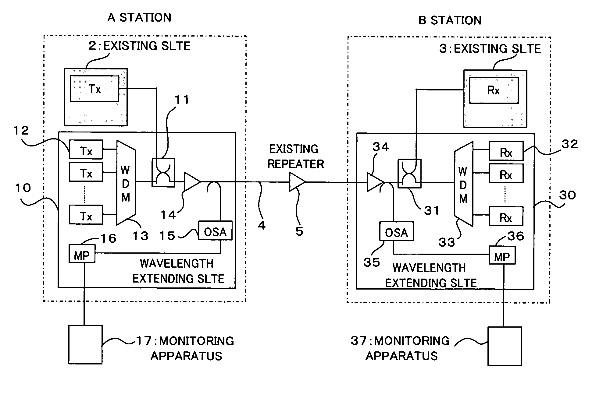
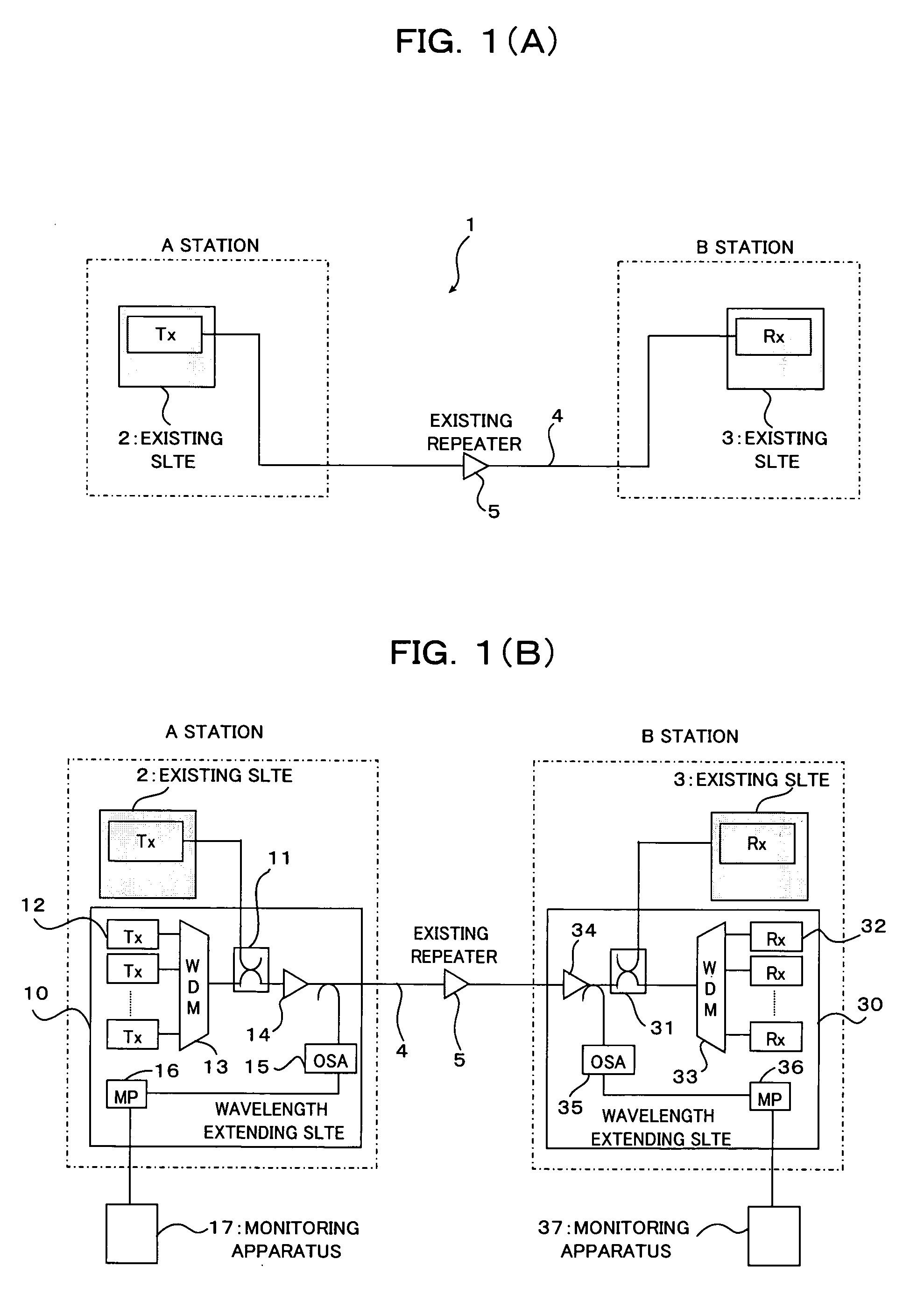
[0031]FIG. 1(A) shows a configuration of an existing optical submarine cable system, and FIG. 1(B) shows a configuration where new wavelength extension is performed for the existing optical submarine cable system of FIG. 1(A).

[0032] As shown in FIG. 1(A), in the existing optical submarine cable system (hereinafter referred to as existing system) 1, an A station as a terminal and a B station as another terminal include optical submarine terminal equipments (hereinafter referred to as exi...


PUM


Abstract

A terminal apparatus by which, even where BER data, for example, of an optical signal of an existing wavelength cannot be utilized, the optical output powers of the existing wavelength and an extension wavelength can be adjusted in a short period of time while eliminating quality degradation of the existing circuit. The terminal apparatus includes a level controlling section for controlling a total optical output power of an existing wavelength signal light and an extension wavelength signal light to a fixed level, a monitoring unit capable of monitoring the optical output power for each wavelength, and a controller for controlling the optical output power of the extension wavelength signal light so that the optical output power of the existing wavelength signal light monitored by the monitoring unit may not be lower than a minimum permissible optical output power.

Description

CROSS REFERENCE TO RELATED APPLICATIONS [0001] This application is based on and hereby claims priority to Japanese Application No. 2004-75913 filed on Mar. 17, 2004 in Japan, the contents of which are hereby incorporated by reference. BACKGROUND OF THE INVENTION [0002] 1) Field of the Invention [0003] The present invention relates to a terminal apparatus, a controlling method for optical output power and a computer-readable storage medium having an optical output power controlling program stored thereon, suitable for use where a wavelength is newly extended in an existing optical transmission system such as, for example, an optical submarine cable system which utilizes an optical amplification submarine repeater. [0004] 2) Description of the Related Art [0005] In recent years, extension of a new wavelength is carried out for an existing optical transmission system such as, for example, an optical submarine cable system utilizing a wavelength division multiplexing (hereinafter referr...

Claims


Application Information

Patent Timeline
IPC IPC(8): H04B10/07H04B10/077H04B10/079H04B10/25H04B10/2507H04B10/294H04B17/00H04J14/00H04J14/02
CPCH04B10/077H04J14/0221H04B10/07955
Inventor YAMAGUCHI, KATSUJISHINMURA, KENICHINAGAYAMA, MASATOTAKADA, TADAYUKI
Owner FUJITSU LTD
Why Eureka
Try Eureka