

Method for Creating Low Pressure In A Brake Activation Device of a Motor Vehicle Brake System
- Summary
- Abstract
- Description
- Claims
- Application Information
AI Technical Summary
Benefits of technology
Problems solved by technology
Method used
Image

Examples
Embodiment Construction
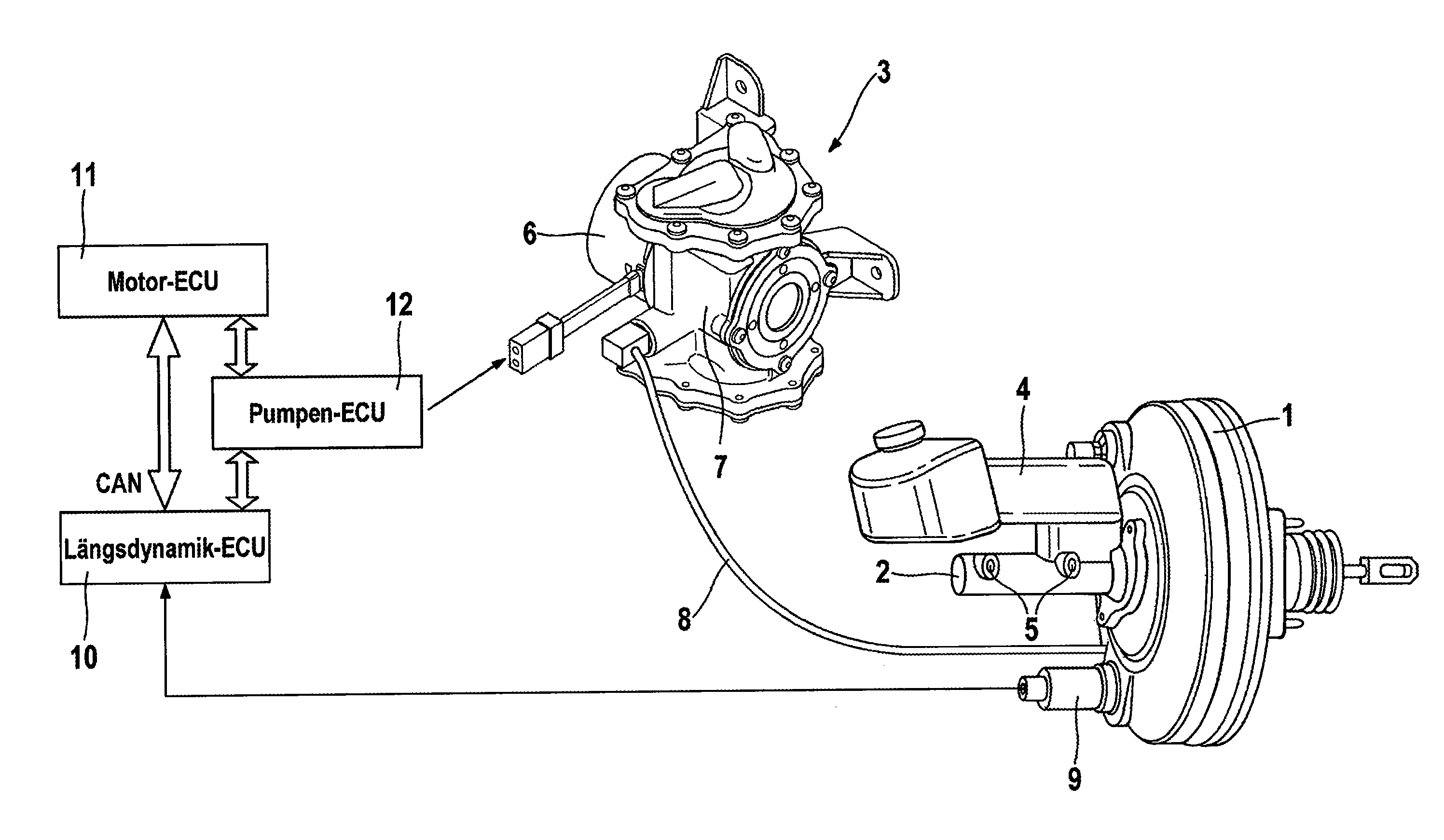
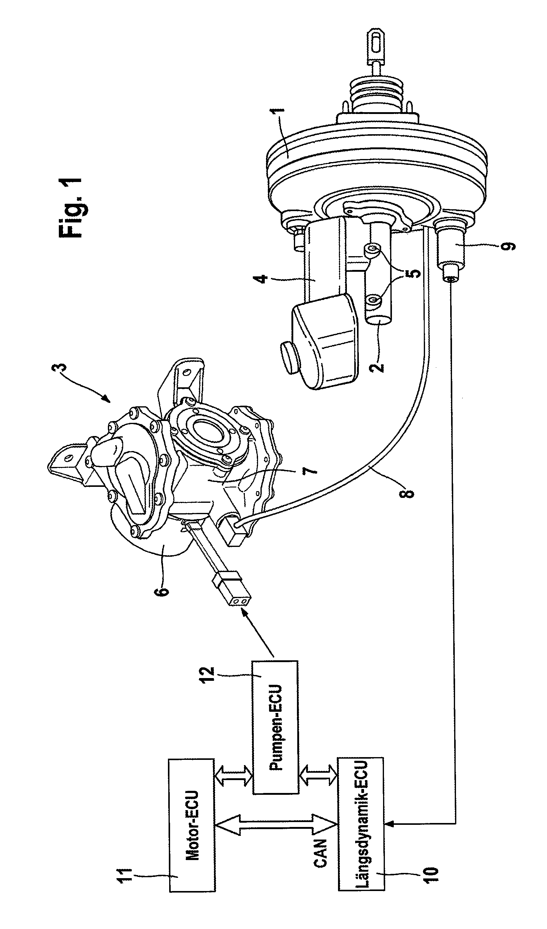
[0020]FIG. 1 shows a schematic system structure of a brake activation device of a motor vehicle brake system.
[0021]It can be seen that the brake activation device for carrying out the method according to aspects of the invention comprises a pneumatic brake force booster 1, a brake master cylinder 2 arranged thereon and a pneumatic motor pump unit 3. Because the basic structure and operation of the brake activation device are generally known, only the features essential to the invention are described hereinafter.
[0022]The vehicle brake system is, for example, of the “brake-by-wire” type and can be activated independently of driver wish by means of an electronic control unit (ECU), that is, driver-independently, and also partially by means of a brake pedal (not shown) (mechanical fall-back level).
[0023]An interior (not shown) of the brake force booster 1 is divided by at least one movable wall into at least one low-pressure chamber and at least one working chamber. The brake master cy...
PUM
 Abstract
Description
Claims
Application Information