Liquid Crystal Display Device and Method for Driving Same

a technology of liquid crystal display and display device, which is applied in the direction of static indicating device, instruments, etc., can solve the problems that the liquid crystal display device might suffer some failure, and achieve the effects of preventing any reduction in the quality of the moving image being displayed, simple circuit configuration, and preventing any fringes

Inactive Publication Date: 2009-10-29
SHARP KK
View PDF7 Cites 31 Cited by
  • Summary
  • Abstract
  • Description
  • Claims
  • Application Information

AI Technical Summary

Benefits of technology

[0044]According to the first or eighth aspect of the present invention, the correction is differentially performed in accordance with the polarity of the voltage applied to the data signal lines, and therefore it is possible to suitably control the change in pixel brightness regardless of the polarity of the applied voltage, thereby preventing any fringes from being generated while displaying moving images. Thus, it is possible to prevent any reduction in quality of the moving images being displayed.
[0045]According to the second aspect of the present invention, there is provided the correction process portion for reading the correction value from the conversion table and outputting it as the correction video signal, and therefore it is possible to prevent any fringes from being generated while displaying moving images with a simple circuit configuration.
[0046]According to the third aspect of the present invention, there are provided the conversion table having the correction values stored therein in association with combinations of value ranges for the video signal, and the correction process portion for subjecting the correction value being read from the conversion table to a predetermined operation and outputting it as the correction video signal, and therefore it is possible to prevent any fringes from being generated while displaying moving images, although the size of the conversion table is reduced.
[0047]According to the fourth aspect of the present invention, there is provided the correction process portion for differentially performing the correcting operation in accordance with the polarity of the applied voltage, and therefore it is possible to prevent any fringes from being generated while displaying moving images without using any conversion table.
[0048]According to the fifth or sixth aspect of the present invention, the correcting circuit differentially performs the correction in accordance with the polarity-reversing signal supplied from the display control circuit or the signal source, and therefore it is possible to prevent any fringes from being generated while displaying moving images with a simple circuit configuration.
[0049]According to the seventh aspect of the present invention, for the pixels to which the voltage with positive polarity is applied so that their brightness does not change sufficiently, the degree of overshoot is intensified to compensate for the change in brightness, whereas for the pixels to which the voltage with negative polarity is applied so that their brightness changes excessively, the degree of overshoot is reduced to keep down the change in brightness. In such a manner, the correction is differentially performed in accordance with the polarity of the voltage applied to the data signal lines, and therefore it is possible to suitably control the change in pixel brightness regardless of the polarity of the applied voltage, thereby preventing any fringes from being generated while displaying moving images.

Problems solved by technology

When a voltage with the same polarity is continuously applied to pixels, liquid crystal display devices might suffer some failure, such as burn-in, and therefore they employ drive methods in which the polarity of the voltage applied to the pixels is changed every predetermined period.

Method used


Image

  • Liquid Crystal Display Device and Method for Driving Same
  • Liquid Crystal Display Device and Method for Driving Same
  • Liquid Crystal Display Device and Method for Driving Same

Examples


first embodiment

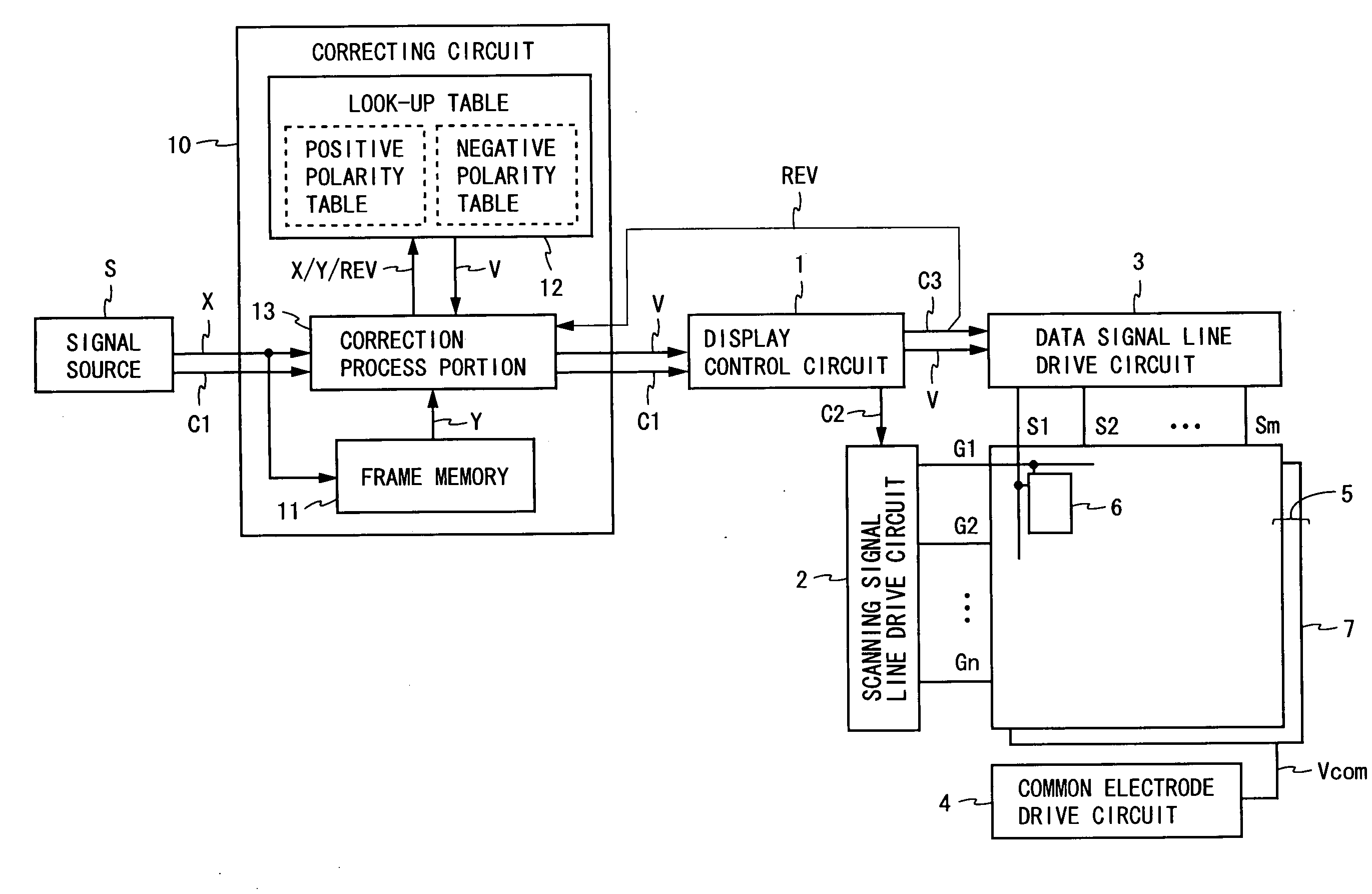
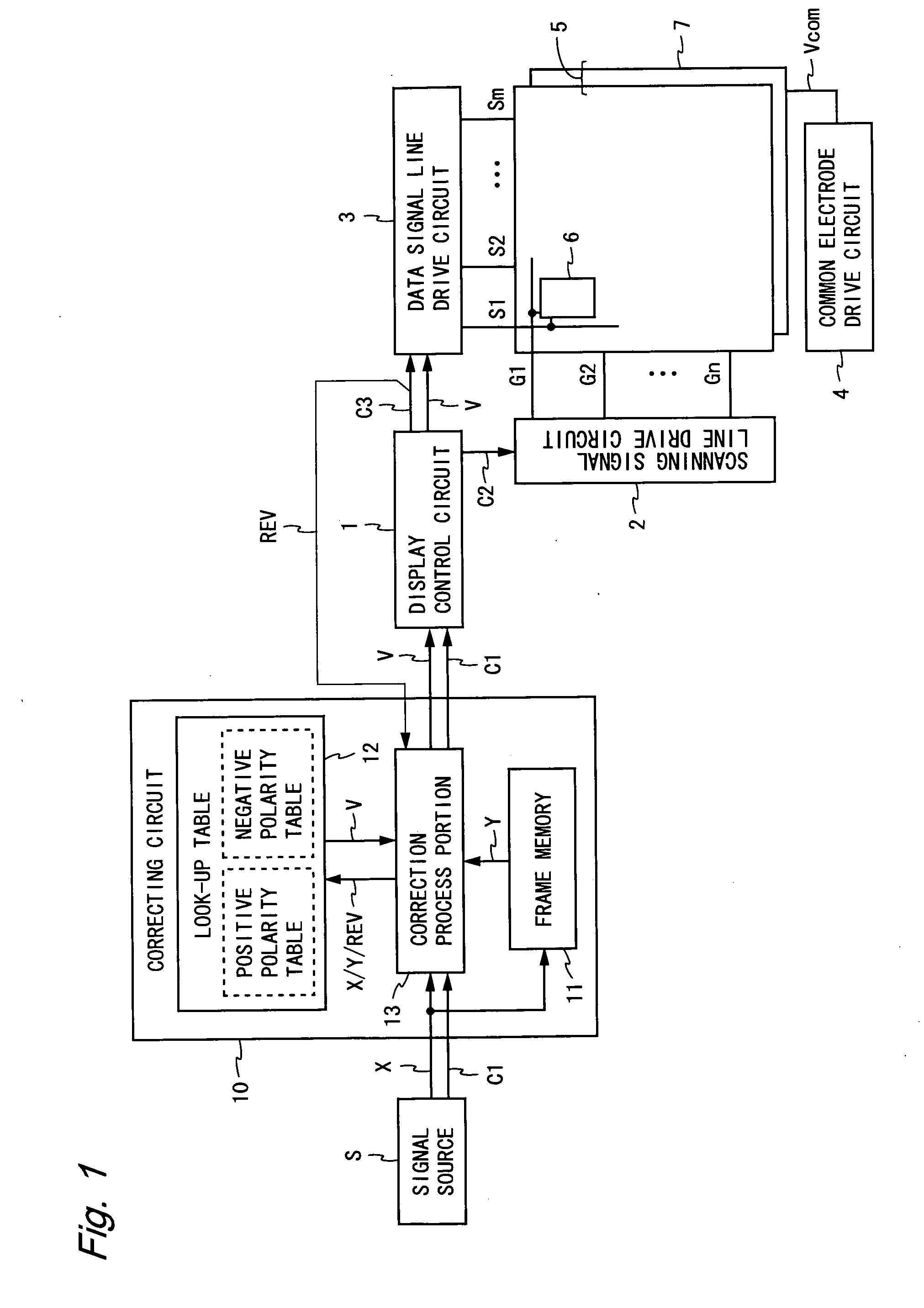
[0091]FIG. 1 is a block diagram illustrating the configuration of a liquid crystal display device according to a first embodiment of the present invention. The liquid crystal display device shown in FIG. 1 includes a correcting circuit 10, a display control circuit 1, a scanning signal line drive circuit 2, a data signal line drive circuit 3, a common electrode drive circuit 4, and a pixel array 5. This liquid crystal display device displays a screen by performing line inversion drive and overshoot drive. The following description will be given on the assumption that the liquid crystal display device shown in FIG. 1 is a normally-black liquid crystal display device.

[0092]In FIG. 1, a signal source S is provided outside the liquid crystal display device, and supplies a video signal X and a control signal C1 to the liquid crystal display device. The control signal C1 includes a clock signal CK, a horizontal synchronization signal HSYNC, a vertical synchronization signal VSYNC, etc. Th...

second embodiment

[0112]FIG. 6 is a block diagram illustrating the configuration of a liquid crystal display device according to a second embodiment of the present invention. The liquid crystal display device shown in FIG. 6 includes a correcting circuit 20, in place of the correcting circuit 10 of the liquid crystal display device according to the first embodiment. In the present embodiment, the same elements as those in the first embodiment are denoted by the same reference characters, and any descriptions thereof will be omitted.

[0113]The correcting circuit 20 includes a frame memory 11, a look-up table 22, and a correction process portion 23. The look-up table 22 has a reduced amount of data compared to the look-up table 12 according to the first embodiment, and has stored therein correction values emphasizing the temporal signal change, in association with combinations of value ranges for the video signal, as well as voltage polarities. The look-up table 22 includes a positive polarity table and...

third embodiment

[0121]FIG. 9 is a block diagram illustrating the configuration of a liquid crystal display device according to a third embodiment of the present invention. The liquid crystal display device shown in FIG. 9 includes a correcting circuit 30, in place of the correcting circuit 10 of the liquid crystal display device according to the first embodiment. In the present embodiment, the same elements as those in the first embodiment are denoted by the same reference characters, and any descriptions thereof will be omitted.

[0122]The correcting circuit 30 includes a frame memory 11, and a correction process portion 33. The correction process portion 33 receives the current-frame video signal X and the previous-frame video signal Y, and also receives the polarity-reversing signal REV outputted from the display control circuit 1 to the data signal line drive circuit 3. The correction process portion 33 executes the process shown in FIG. 10 based on these input signals.

[0123]First, the correction...


PUM


Abstract

A drive circuit of a liquid crystal display device performs line inversion drive based on a correction video signal V. A look-up table (12) includes two types of tables having stored therein correction values for use in overshoot drive. Based on a current-frame video signal X, a previous-frame video signal Y stored in a frame memory (11), and a polarity-reversing signal REV, a correction process portion (13) reads a correction value from the look-up table (12), and outputs the correction value being read as the correction video signal V. In such a manner, a correcting circuit (10) is used to control the degree of overshoot in accordance with the polarity-reversing signal REV. Thus, it is possible to suitably control the change in pixel brightness regardless of the polarity of the applied voltage, thereby preventing any fringes from being generated while displaying moving images.

Description

TECHNICAL FIELD[0001]The present invention relates to liquid crystal display devices, and particularly to a liquid crystal display device that performs line inversion drive, and a method for driving the same.BACKGROUND ART[0002]When a voltage with the same polarity is continuously applied to pixels, liquid crystal display devices might suffer some failure, such as burn-in, and therefore they employ drive methods in which the polarity of the voltage applied to the pixels is changed every predetermined period. Examples of the methods used include frame inversion drive in which the voltage polarity is changed every frame, line inversion drive in which the voltage polarity is changed every line or every several lines, and dot inversion drive in which the voltage polarity is changed for each pixel. Also, in order to improve response speed, some liquid crystal display devices perform overshoot drive (also referred to as “overdrive” or “overdriving”), applying a voltage higher or lower tha...

Claims


Application Information

Patent Timeline
Patent Type & Authority Applications(United States)
IPC IPC(8): G09G3/36
CPCG09G3/3614G09G3/3648G09G2340/16G09G2320/0261G09G2320/0285G09G2320/0252
Inventor TAKAHASHI, KOZOYAMATO, ASAHINAKAGAWA, KIYOSHIKAWAI, TAKAAKI
Owner SHARP KK
Why Eureka
Try Eureka