Material conveyance device and material conveyance method

a technology of material conveyancing and material conveyancing, which is applied in the direction of conveyors, bulk conveyors, transportation and packaging, etc., can solve the problems of material stagnation, material quality degradation, and change of air speed or pressure in pipes

Inactive Publication Date: 2016-04-07
MATSUI MFG
View PDF25 Cites 31 Cited by
  • Summary
  • Abstract
  • Description
  • Claims
  • Application Information

AI Technical Summary

Problems solved by technology

Conversely, if the air speed in the pipe is high, the material rubs in the pipe and this causes snaking or whiskers on the material, so that the quality of the material is degraded.
Moreover, there are cases where change of the kind of the material to be pneumatically conveyed changes the specific gravity and the like of the material and this changes the pipe resistance or pressure to cause stagnation of the material.
Moreover, change

Method used


Image

  • Material conveyance device and material conveyance method
  • Material conveyance device and material conveyance method
  • Material conveyance device and material conveyance method

Examples


Embodiment Construction

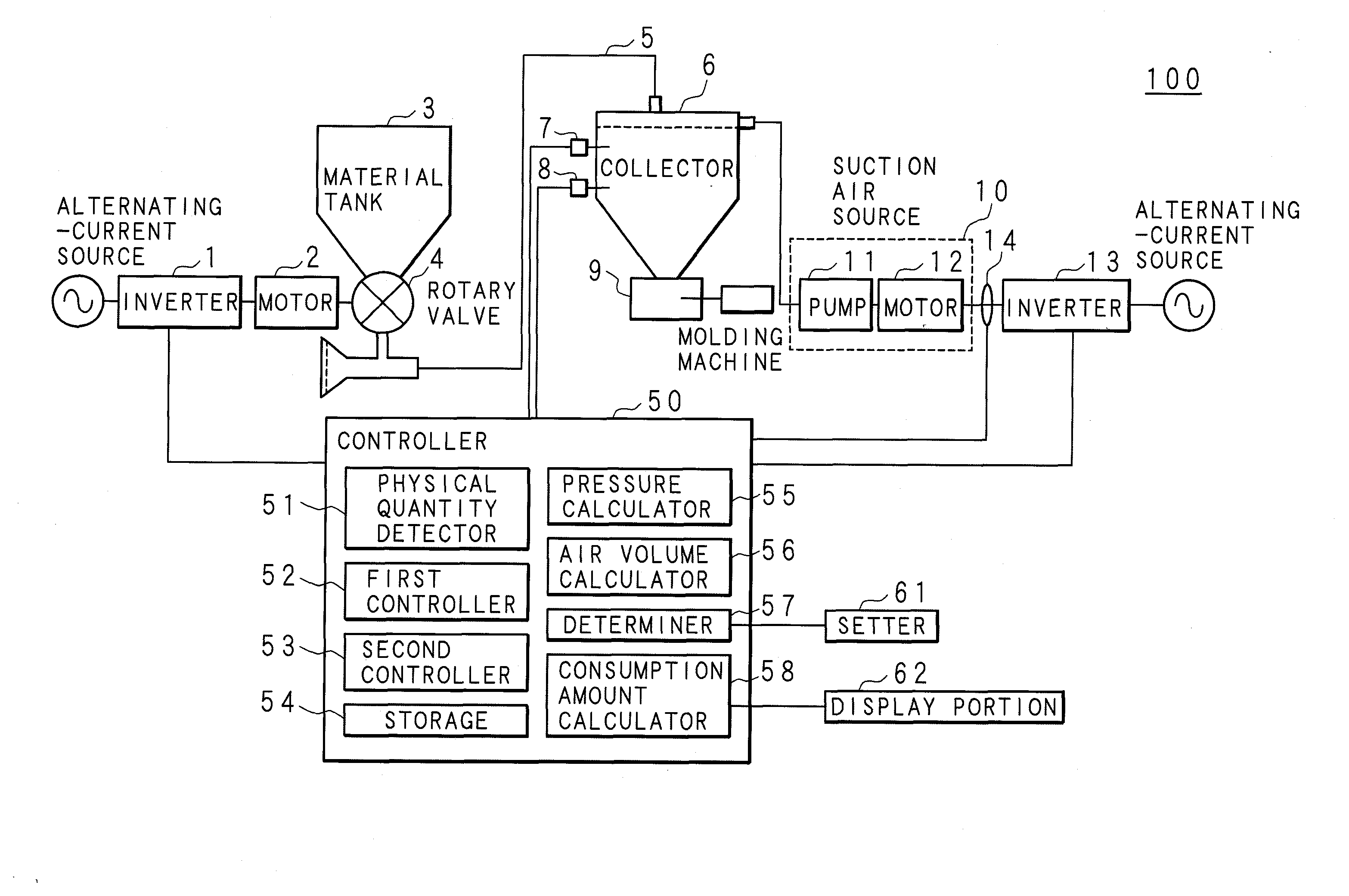
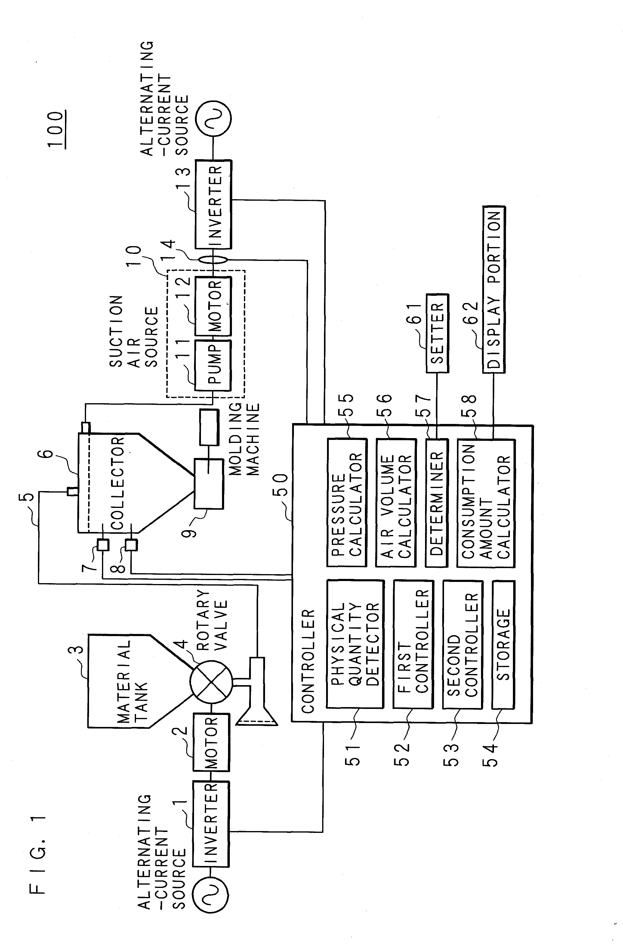
[0057]Hereinafter, the present invention will be described based on the drawings showing an embodiment thereof. FIG. 1 is an explanatory view showing an example of the structure of a material conveyance device 100 of the present embodiment. As shown in FIG. 1, the material conveyance device 100 includes an inverter 1 as the material supply inverter, a motor 2, a material tank 3, a rotary valve 4, a collector 6 as the accommodation portion, a suction air source 10, an inverter 13, and a controller 50. The suction air source 10 has a pump 11 and a motor 12 as the electric motor. The material tank 3, the motor 2 and the rotary valve 4 as the material container constitute the material supply portion. The outlet of the rotary valve 4 provided below the material tank 3 and the collector 6 are interconnected by a pipe 5 for pneumatically conveying a material (for example, a powder and granular material). A molding machine 9 is provided at the outlet of the collector 6.

[0058]A level meter 8...


PUM


Abstract

A material conveyance device that has an inverter converting a frequency of an alternating-current source and a suction air source having an electric motor driven by the inverter and pneumatically conveys a material by the suction air source through a pipe for conveying the material, includes: a physical quantity detector that detects a physical quantity related to an output of the inverter; and a controller that controls an air volume or an air speed by the suction air source based on the physical quantity detected by the physical quantity detector.

Description

CROSS-REFERENCE TO RELATED APPLICATIONS[0001]This application is the national phase under 35 U.S.C. §371 of PCT International Application No. PCT / JP2013 / 059468 which has an International filing date of Mar. 29, 2013 and designated the United States of America.BACKGROUND[0002]1. Technical Field[0003]The present invention relates to a material conveyance device that has an inverter converting the frequency of an alternating-current source and a suction air source having an electric motor driven by the inverter and pneumatically conveys a material by the suction air source through a pipe for conveying the material, and a material conveyance method.[0004]2. Description of Related Art[0005]Conventionally, a material conveyance device has been in practical use in which a material (for example, a powder and granular material) pneumatically conveyed from a material supply source is collected with a collector or the like and accommodated, and the material pneumatically conveyed through an in...

Claims


Application Information

Patent Timeline
IPC IPC(8): B65G53/66B65G53/26
CPCB65G53/26B65G53/66
Inventor HANAOKA, KAZUNARIYAMASHITA, SAIJIMATSUDA, TAKAHIRO
Owner MATSUI MFG
Why Eureka
Try Eureka