Calibration Method of Antenna Omnidirectional Combining System

A calibration method and antenna technology, which is applied to antennas, antenna arrays, antenna components, etc., can solve the problems of difficult antenna omnidirectional synthesis technology

Active Publication Date: 2018-07-06
DFINE TECH
View PDF3 Cites 0 Cited by
  • Summary
  • Abstract
  • Description
  • Claims
  • Application Information

AI Technical Summary

Problems solved by technology

[0003]The omnidirectional synthesis technology of this antenna is quite difficult. At present, no other company in China has successfully realized the omnidirectional synthesis technology of this directional antenna. Only in the past two years in Europe and the United States A few large companies have launched related products, but their technical implementation details are also kept secret

Method used


Image

  • Calibration Method of Antenna Omnidirectional Combining System
  • Calibration Method of Antenna Omnidirectional Combining System

Examples


Embodiment 1

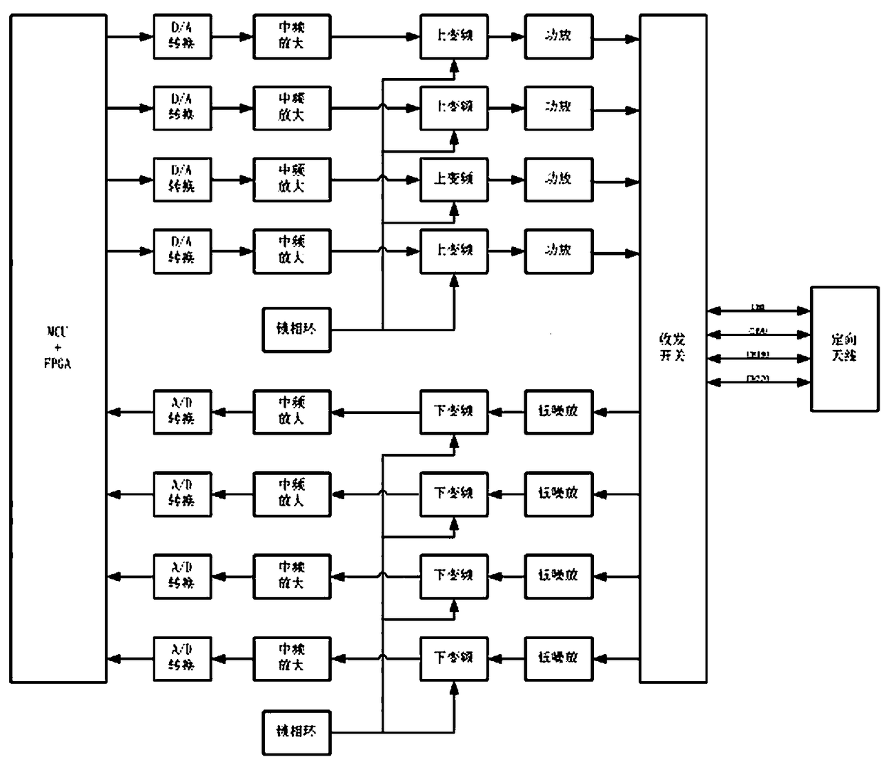
[0103] Such as figure 1 As shown, the transceiver includes 4 transmitting channels and 4 receiving channels, which are respectively connected to the 0º antenna, 90º antenna, 180º antenna, and 270º antenna of the directional antenna through the transceiver switch. DA sampling clock 400MHz, output 80MHz transmit digital intermediate frequency, AD sampling clock 100MHz, sampling receiving 120MHz intermediate frequency, both sending and receiving adopt one frequency conversion, the channel structure is simple. The whole machine adopts the same reference clock to ensure the same source of sending and receiving signals, which is beneficial to eliminate frequency difference and phase calibration. The MCU and FPGA jointly complete the amplitude / phase control of the transmitting antenna and realize the omnidirectional synthesis of the antenna.

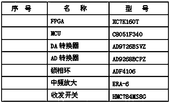
[0104] The present invention has been used in a new type of secondary radar module developed by our company. Table 1 shows the main component...


PUM


Abstract

The invention discloses an omnidirectional antenna synthesis system, so as to solve the problems of inaccurate phase and amplitude control when omnidirectional beam transmission is formed for a directional antenna and signals are transmitted to four channels of the antenna. A transceiver comprises four transmitting channels and four receiving channels connected with a 0-DEG antenna, a 90-DEG antenna, a 180-DEG antenna and a 270-DEG antenna of the directional antenna through transmitting and receiving switches respectively. A DA sampling clock has a frequency of 400MHz, an 80MHz transmitting digital intermediate frequency is outputted, an AD sampling clock has a frequency of 100MHz, A 120MHz intermediate frequency is sampled and received, transmitting and receiving both adopt one-time variable frequency, and each channel has a simple structure. The overall machine adopts one reference clock, transmitting signals and receiving signals are ensured to have the same source, and frequency difference elimination and phase calibration are facilitated. An MCU and an FPGA together complete amplitude / phase control on the transmitting antenna, and antenna omnidirectional synthesis is realized.

Description

Technical field: [0001] The present invention is related to a system for controlling the phase and amplitude of 4 channel transmission signals of a directional antenna to form an omnidirectional beam transmission. Background technique: [0002] The airborne antenna of a certain type of airborne secondary radar is a directional antenna, and the antenna is installed on the top and bottom of the aircraft. The antenna can form directional beams in four 90º directions, and is connected to the transceiver using four coaxial cables. The transceiver transmits the inquiry signal and receives the response signal through the antenna. Now it is required to use this directional antenna to form omnidirectional beam transmission, and it is necessary to precisely control the phase and amplitude of the 4 channel transmission signals of the antenna. [0003] The omnidirectional synthesis technology of this antenna is relatively difficult. At present, no other company in China has successful...

Claims


Application Information

Patent Timeline
Patent Type & Authority Patents(China)
IPC IPC(8): H01Q1/28H01Q3/26H01Q21/00H01Q25/02H01Q1/50
CPCH01Q1/285H01Q3/26H01Q21/0006H01Q25/02
Inventor 吴帮学
Owner DFINE TECH
Why Eureka
Try Eureka