A dynamic compaction machine and its guideable lifting mechanism

A technology of dynamic tamping machine lifting and dynamic tamping machine, applied in soil protection, infrastructure engineering, construction, etc., can solve problems such as rope 5 detachment, boom deformation movement, collision interference, etc., to achieve simple manufacturing process and stable work Good performance and high structural reliability

Active Publication Date: 2015-12-23
SANY HEAVY IND CO LTD (CN)
View PDF6 Cites 0 Cited by
  • Summary
  • Abstract
  • Description
  • Claims
  • Application Information

AI Technical Summary

Problems solved by technology

During the tamping process of the rammer G, strong impact and vibration will be generated on the arm frame, which will cause deformation of the arm frame and affect the movement of the oil cylinder 1 and the movable pulley block 3
[0005] On the one hand, the linear motion of the movable pulley block 3 in the front and rear directions is unstable due to the up and down fluctuations, which reduces the stability of the movable pulley block 3 movement, and even causes collision interference between the movable pulley block 3 and the jib in severe cases, and may also cause the rope 5 Separate from the movable pulley block 3; on the other hand, for the oil cylinder 1, the piston rod will be suffocated due to the unbalanced load, which will affect the reliability and sealing of the oil cylinder 1 after frequent dynamic compaction construction

Method used


Image

  • A dynamic compaction machine and its guideable lifting mechanism
  • A dynamic compaction machine and its guideable lifting mechanism
  • A dynamic compaction machine and its guideable lifting mechanism

Examples


Embodiment Construction

[0032] In order to understand the above-mentioned purpose, features and advantages of the present invention more clearly, the present invention will be further described in detail below in conjunction with the accompanying drawings and specific embodiments.

[0033] In the following description, many specific details are set forth in order to fully understand the present invention, but the present invention can also be implemented in other ways different from those described here, therefore, the present invention is not limited to the specific embodiments disclosed below limit.

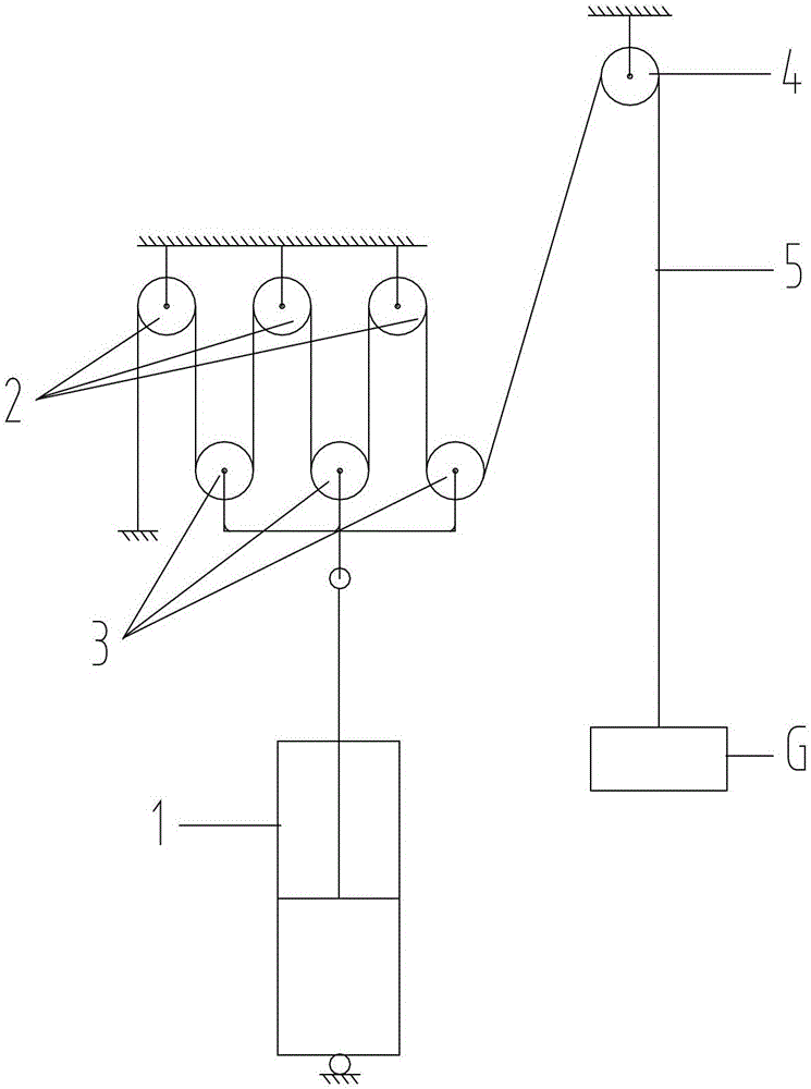
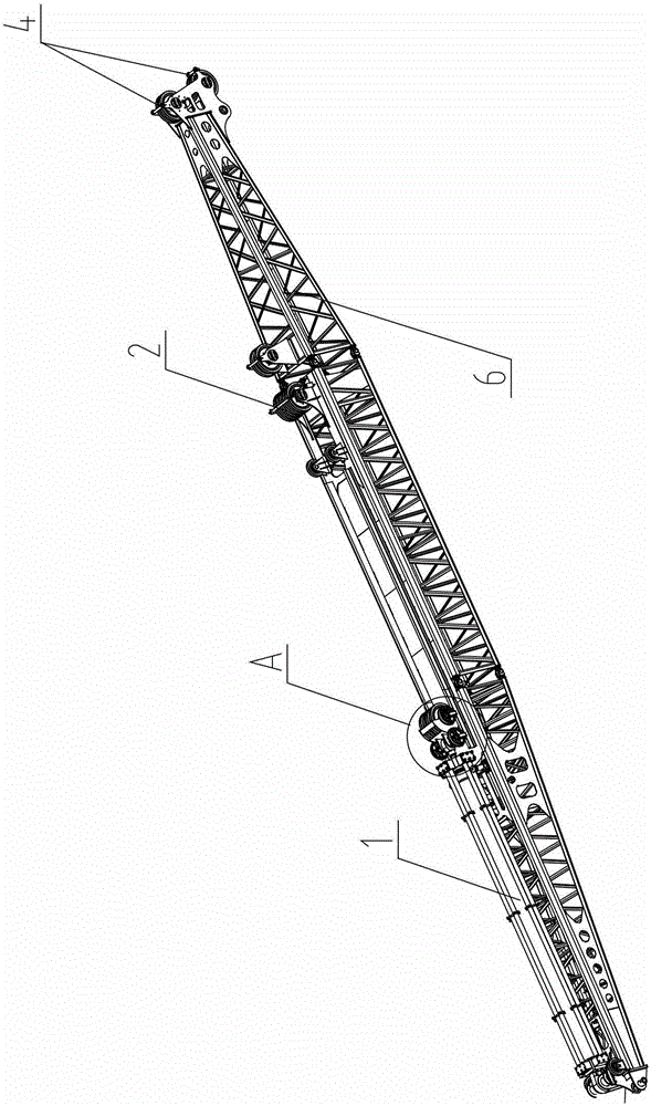
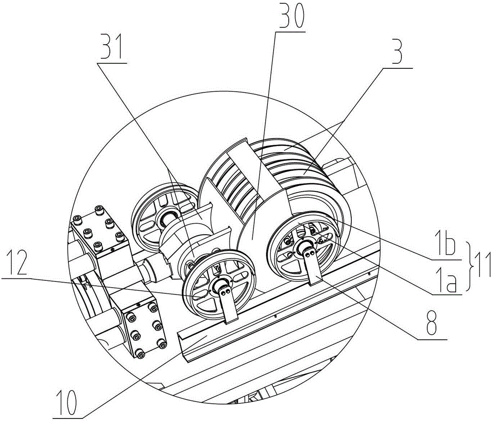
[0034] figure 2 Shown is a schematic structural view of the arm frame provided with the lifting mechanism of the dynamic compaction machine according to an embodiment of the present invention, image 3 yes figure 2 Enlarged view of region A in the middle. The lifting mechanism of the dynamic compaction machine of this embodiment includes an oil cylinder 1, a movable pulley block 3, and a fixed pu...


PUM


Abstract

The present invention proposes a dynamic compaction machine and its guideable lifting mechanism. The lifting mechanism includes an oil cylinder, a fixed pulley block and a movable pulley block, and also includes a guide rail and a guide moving part. The guide rail is fixed, and the guide move part is limited. It is located on the guide rail and can move along the guide rail, and the guide moving part is connected with the moving pulley block and / or the oil cylinder. The lifting mechanism of the dynamic compaction machine can effectively support and restrain the movable pulley block, and has the advantages of high reliability, good maintainability, easy implementation, good stability and the like.

Description

technical field [0001] The present invention mainly relates to the field of engineering machinery, in particular to a guideable lifting mechanism of a dynamic compaction machine and a dynamic compaction machine including the lifting mechanism. Background technique [0002] Dynamic tamping machine is a kind of construction machinery used for impact compaction of materials or foundations, widely used in the construction of industrial and civil buildings, warehouses, yards, docks, airports, road and railway roadbeds, artificial islands, etc. . [0003] The Chinese patent application with the application number 201210478723.3 and titled "A Cylinder-Driven Dynamic Compactor Lifting Mechanism and Dynamic Compactor" discloses a dynamic compaction machine lifting mechanism, and its structural principle diagram is as follows figure 1 As shown, it includes an oil cylinder 1, a fixed pulley block 2, a movable pulley block 3 and a rope 5 for connecting a rammer G, wherein: the first en...

Claims


Application Information

Patent Timeline
Patent Type & Authority Patents(China)
IPC IPC(8): E02D3/068
Inventor 易小刚李东吴志强权哲奎
Owner SANY HEAVY IND CO LTD (CN)
Why Eureka
Try Eureka