Valve core structure of water heater

A water heater and valve core technology, which is applied to multi-port valves, valve devices, engine components, etc., can solve the problems of unsatisfactory sealing performance, affecting bathing comfort, and large overall structure, and achieves simple and compact structure design and flow path design. Scientific and reasonable effect that meets comfort requirements

Active Publication Date: 2013-07-17
广东新威博电器有限公司
View PDF9 Cites 1 Cited by
  • Summary
  • Abstract
  • Description
  • Claims
  • Application Information

AI Technical Summary

Problems solved by technology

The manual valve and the automatic electronic valve are usually two independent valve bodies, which are installed on the hot and cold water faucet. The two valve bodies form an independent mixed water channel to connect with the water inlet and outlet ports, which makes the overall structure relatively large and the sealing performance is not ideal.
[0003] On the other hand, the outlet water temperature adjustment of the water heater is realized by adjusting the cold water flow or hot water flow. The general method is to use one of the flow as a fixed value, and adjust the other water flow to achieve the mixed water temperature. In this way, when the user needs a relatively high water temperature, the flow rate is often too small, which affects the comfort of bathing

Method used


Image

  • Valve core structure of water heater
  • Valve core structure of water heater
  • Valve core structure of water heater

Examples


Embodiment Construction

[0027] The present invention will be further described below in conjunction with the drawings and specific embodiments.

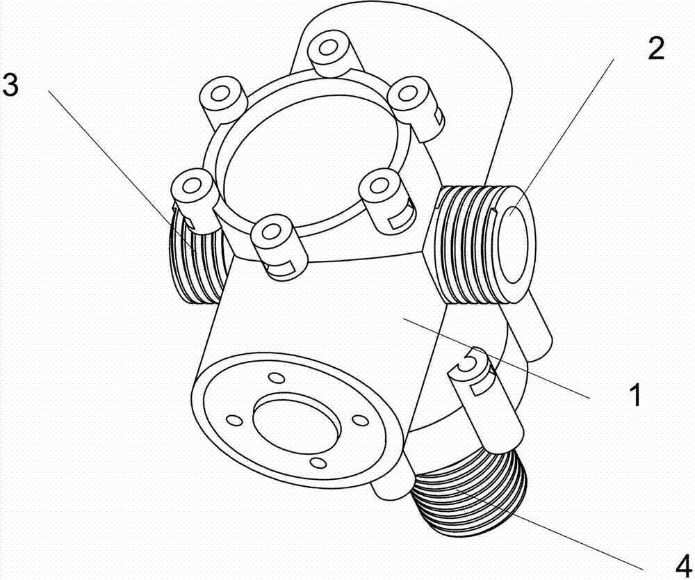
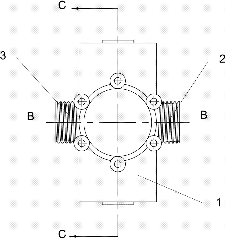
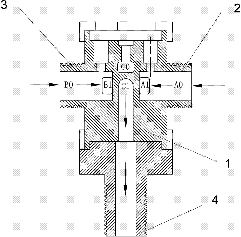
[0028] See figure 1 —6. A water heater valve core structure, including an integral valve body, which are respectively arranged in the automatic valve cavity 5 and manual valve cavity 6 of the valve body and the automatic valve core and the movable valve core. The valve body is also provided with a cold water pipe port 2. Hot water pipe port 3, water outlet pipe port 4, cold water pipe port 2 is the cold water flow channel A0 connected to tap water, and hot water pipe port 3 is the hot water flow channel B0 and water outlet pipe port connected to the inner tank of the water heater 4 is the outlet flow channel C1 leaving the valve body. The valve body 1 is provided with an automatic valve chamber 5 and a manual valve chamber 6; an automatic valve core is provided in the automatic valve chamber, and a manual valve core is provided in the manual valve chamber; the...


PUM


Abstract

The invention discloses a valve core structure of a water heater. The valve core structure comprises an automatic valve core and a hand-operated valve core arranged in an automatic valve cavity and in a hand-operated valve cavity, wherein the automatic valve core and the hand-operated valve core comprise valve core shells, bases, moving pieces, fixed pieces and valve core rotating handles; the valve core rotating handles are connected to the moving pieces in a clamping manner, each fixed pieces is provided with a first valve port, a second valve port, a third valve port and a fourth valve port, each moving piece is provided with a groove cavity, the center round part of the groove cavity and the first valve port of each fixed piece are correspondingly arranged, and a fan part of the groove cavity and the second valve port and the third valve port on each fixed piece are positioned on the same circumference line; and the second valve port and the third valve port are respectively communicated with a hot water flow channel and a cold water flow channel of a valve body, the valve body is internally provided with a mixing water flow channel so that the fourth valve port of the fixed piece of the automatic valve core and the fourth valve port of each fixed piece are communicated, and the first valve port of the fixed piece of the hand-operated valve core is communicated with a water outlet flow channel of the valve body. The valve core structure provided by the invention meets a scouring bath use comfort requirement.

Description

Technical field [0001] The invention relates to the technical field of domestic or commercial water heaters, and more specifically, to a water heater valve core structure applied to a water heater. Background technique [0002] At present, all electric water heaters on the domestic market realize the control of the outlet temperature by adjusting the flow of cold and hot water. High-end products generally have a temperature setting function, and the temperature setting usually refers to the water temperature of the water heater inner tank. The setting is not a direct setting of the outlet water temperature. The final outlet water temperature is adjusted manually or automatically through an external mixing valve. The manual valve and the automatic electronic valve are usually two independent valve bodies, which are installed on the hot and cold water faucet. The two valve bodies form an independent water mixing channel to connect with the water inlet and outlet ports, making the ...

Claims


Application Information

Patent Timeline
IPC IPC(8): F16K11/22
Inventor 殴永源吴宇翔董越彭武龙欧阳山西
Owner 广东新威博电器有限公司
Why Eureka
Try Eureka